Introduction
Modern communication networks such as LTE and 5G NR are the result of a continuous evolution in search for more efficient communication: in a nutshell transmit (and receive) the biggest amount of information in the shortest possible time.
However, the concepts needed for a complete understanding are many, and are somewhat complex.
Let’s try to understand how everything works from a simpler point of view, looking to do analogies with real-life examples, and try to assimilate such concepts in a natural way.
The understanding of these basic concepts, instead of understanding calculations only, brings us several advantages and built a solid foundation that will certainly help in the future.
So, let’s go and try to understand today, in an easy way, some of the main concepts of LTE and 5G NR networks?
Communication
The most basic and important concept to be understood when you want to learn a new communication technology is how data is transported from a point to other.
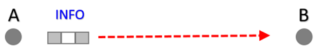
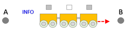
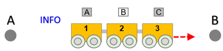
We can understand communication as the transport of information from one place to another. Given a certain information (INFO), how does it go from point A to point B.
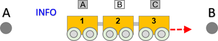
We can represent the same above figure, but now with the main elements of a radio access network: a user equipment (UE) and a base station (BS). And of course, our data (1’s and 0’s or ABC) already represented.
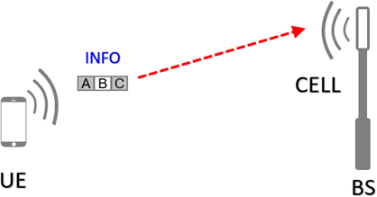
For the above communication to happen, several transformations are necessary to convert information from the digital to analog world and vice versa, as well as several “standards” need to be followed - and both parties involved need to know about.
In other words, for both parties to “talk”, they need to speak the same language – or more specifically, same protocol.
The information will travel through a physical medium that is always analog (the real world is analog), but will also be logically controlled. Therefore, in all wireless communication we have the definition of physical channels and logical channels.
But let’s not worry now about understanding these concepts, as well as all the complicated modulations and techniques used to obtain better use of the signal (Spectral Efficiency).
Whatever the radio access technology used to communication (2G GSM, 3G UMTS, 4G LTE, 5G NR…) there is a very basic concept and common to all: the physical channel.
We can understand as a physical channel the means by which information will be transformed, in order to be transported.
Transporting information
Going back to our example, we could use a pipe, and directly transport the information from point A to point B.
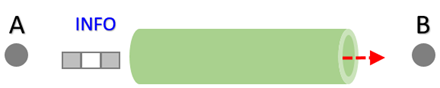
But this analogy would be more related to transport by circuit (the pipe or tube). In our case, in modern networks the communication is made with packets. The information is broken into small pieces, just like small packets.
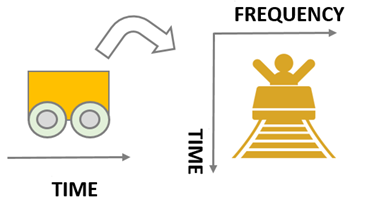
We can make an analogy of transporting packages with transport made by wagons. And in our example, if we broke the information into three parts, we’d need three wagons.
Our information must be broken into pieces according to existing wagons, which follow standard rules and formats.
And the size of the wagon that will carry our information follows a series of standards, in order to have the “best possible size” so that transport can also be done in the best way – for example without delays.
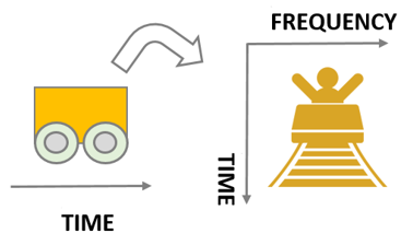
And to understand the “best possible size” of the wagon we need to consider the domains in which the information is represented.
Time and Frequency Domains
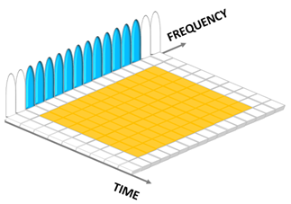
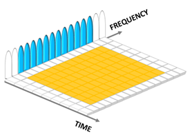
In more advanced networks such as LTE and 5G NR information is not only represented in the Time domain but is also represented in the Frequency domain. (And also, the Amplitude domain, but we can ignore this component for now).
The following figure helps us visualize this concept - the time-frequency plan.
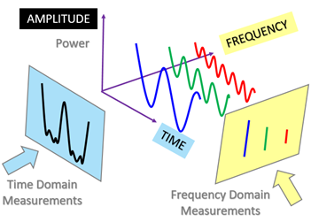
We won’t go into detail for now of why and how this is done, but let’s just consider that the information uses all these domains.
And because it is also represented in the Frequency domain, it follows the rules of a very famous algorithm - Fast Fourier Transform - that allows you to convert a signal from its original domain to a representation in the frequency domain and vice versa. Although it is not simple (we will talk about it in another opportunity) the Fast Fourier Transform greatly facilitates the processing of the signal, which allows us to extract information from it and make it more appropriate for specific applications.
For now, let’s just “accept” that Fast Fourier Transform (or FFT) allows that, instead of working with all the bandwidth being transmitted, we work only with smaller parts of it.
Bandwidth
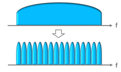
The 3G/WCDMA communication system is a broadband system - it works with the entire band. But as we saw above, this is not recommended, and that is exactly why it has evolved (remember LTE = Long Term “Evolution” ![]() ) and started to divide the band into smaller parts. Broadband communication systems like LTE and 5G NR don’t work with the entire band, but they divide the bandwidth into smaller parts.
) and started to divide the band into smaller parts. Broadband communication systems like LTE and 5G NR don’t work with the entire band, but they divide the bandwidth into smaller parts.
For this, they use for example OFDMA, which allows the distribution of broadband into many (tens to thousands) narrow carriers that will carry the signals, thus obtaining a better spectral efficiency, and a robust resistance to signal degradation.
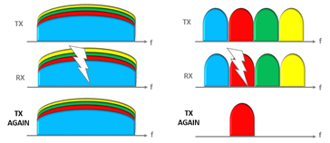
We see in the above example that in case of problems of degradation of the signal (i.e., due to fading), the transmission via several smaller multi carriers is better (only 1/4 of the signal was lost) compared with the single carrier transmission.
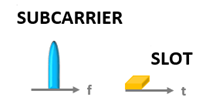
This is exactly what LTE does: it divides a broadband into several narrow carriers, with width of 15 kHz. It is very important to make clear however that this has nothing to do with modulation - it is only one way in which we divide a higher frequency into smaller orthogonal carriers, called subcarriers.
Now that we’ve briefly reviewed some concepts, let’s move on.
Just remembering that signals like LTE and 5G NR involve management of the Frequency, Time, and Code domains.
This is very complex – especially for those who are not very familiar with OFDM/OFDMA (the multiplexing by division of orthogonal frequencies) and that only name already scares. ![]()
So, let’s return to follow our analogy. Then we go back to the technical terms.
Wagon in Time
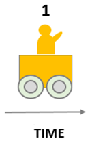
Going back to our analogy and trying to understand how our information behaves in time, we again have the figure of the wagon moving in time.
In our association, the wagon holds a certain amount of information. For example, we may have a seat, and one person can travel in it.
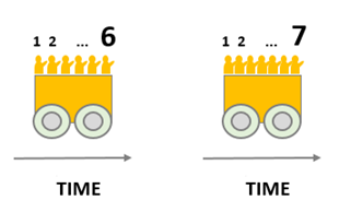
But the wagons can be different – having for example 6 or 7 seats, depending on the “spacing” between the seats.
Wagon in Time and Frequency
Until now in our analogy we used a wagon, in one domain only – Time domain. But we need to proceed with our analogy for the time-frequency plan, where for every moment (in time) we can have several associated frequencies.
So now in our analogy we continue with a wagon that moves in time - but also has seats.
Our wagon can be for two people sitting side by side. Or we could even have a wagon for 12 people, next to each other!
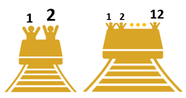
In our example, considering a wagon with 7 seats with 12 people sitting side by side, we would have a wagon moving as below, with 84 people! ![]()
Information in Time and Frequency
In our wagon example, we can consider that each person moving is able to carry information, for example a letter.
Let’s assume that every person who enter the wagon receives a letter and sit in a certain place.
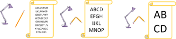
The amount of information in each letter will depend on the conditions of the environment at the exact moment they were written.
It may be for example that some letters have been written in a well-lit place and using a good pencil. In this case, the letters will contain plenty of written words.

But it may be that some of them have been written with a bad (broken) pencil. And in this case, without much precision, the letters had to be written a little bigger, causing the number of words to be smaller.
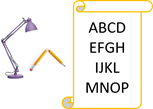
And it may be that some letters have been written in a place with terrible conditions: in a place without enough light and writing with a broken pencil. In this scenario, the letter will contain very few words.

We can consider the “symbols” as the “person” in each place of the wagon.
LTE and 5G NR signals consist of many (tens to thousands) of narrow carriers carrying symbols – just like the wagons can carry people! ![]()
If we understand how information flows in the example we’ve seen so far, then we can understand how this applies to network communication systems like LTE and 5G NR!
And therefore, we can start to introduce some concepts and terminology specific to LTE and 5G NR.
Resources in Time and Frequency
Radio Access Technologies such as LTE and 5G NR have a complex three-dimensional arrangement of resource allocation – time domain, frequency domain and spatial domain. And precisely because of this, many people end up not fully understanding how they work, and simply give up. ![]()
But if we understand how allocation happens in the time-frequency plan the whole arrangement ends up being understood with ease.
So, let’s do it.
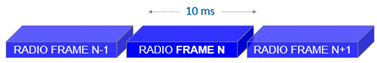
Radio Frame
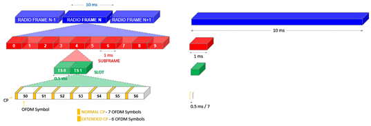
In the Time domain, transmissions are organized in FRAMEs (which in LTE for example is 10 ms long).
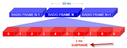
Subframe
Each frame consists of 10 SUBFRAME lasting 1 ms.
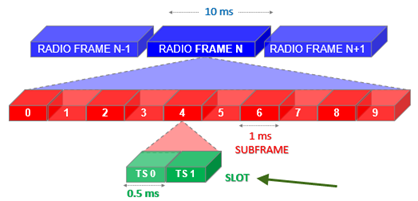
Slot
Each subframe is made of two SLOTs, each one lasting 0.5 ms.
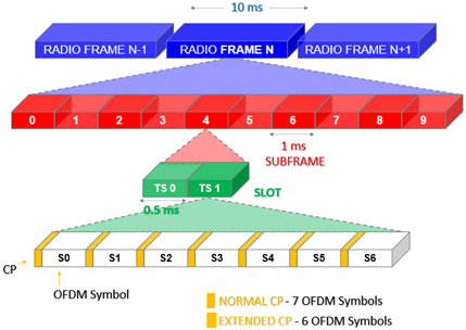
Symbols
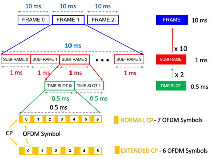
And finally, each slot is made of 7 or 6 OFDM symbols, depending on whether a Short (Normal) or Long (Extended) Cyclic Prefix (CP) was used. (The useful duration of the symbol is fixed, as well as the duration of the slot - for this reason, depending on the size of the CP we will have 6 or 7 symbols).
The CP is created by prefixing each symbol as a copy of the end of the symbol (more details in our tutorial here). Longer CP is useful in environments with large propagation delays.
In the following figure we have also a “somewhat” proportional representation of frame, subframe, and slots sizes.
And we can also make the same representation without the 3D effect, which is what we find most in the documentations.
Right. So far, we’ve talked about the Time domain of time. Now let’s see the terminology in the frequency domain.
Resource Element (RE)
Let’s go back to our example and consider our wagon in the smallest possible configuration - with only one seat.
In the time domain we have the time slots and symbols - the wagon moves in the symbol time!
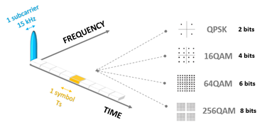
Now, in the frequency domain we have identified that each wagon is associated with a single small carrier (for LTE 15 kHz in LTE).
And the person sitting on it can carry information. The information (bits) is stored as a symbol through modulation (QPSK, 16QAM, 64QAM, 256QAM) depending on the quality of the channel being used in that moment (QPSK = 2 bits, 16QAM = 4 bits, 64QAM = 6 bits,256QAM = 8 bits).
Just like our above example, where the letters were written and the final content was according to the the environment conditions.
So far we have seen the representation of a wagon with only one place. But as we’ve already seen, the wagon may have more seats - for example 12 seats next to each other (each seat associated with an unique and orthogonal subcarrier - of 15 kHz for LTE). And they move in time, for example during for example 0.5 in a slot with 7 symbols.
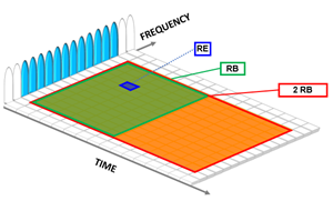
For the above considerations, the representation would be as below.
In the time-frequency plane above, where we represented the time slots, symbols and carriers that make up the signal, the smallest amount of resources we can identify is what we call the Resource Element (RE).
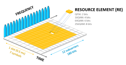
The Resource Element (RE) is the smallest amount of data (modulated by a certain amount of bits) that we can identify, and is formed by a subcarrier and an OFDM symbol.
Resource Block (RB)
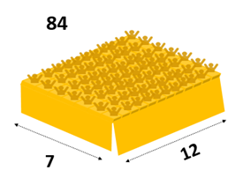
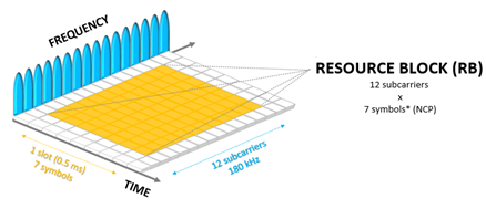
Although the RE is the “smallest part of the signal” (a modulation symbol associated with a subcarrier), the smallest “usable" part of the signal is the Resource Block (RB) - consisting of 12 subcarriers (15 kHz in LTE) and 7 (or 6) symbols.
We say usable (the RB) because it is the smallest unit of resources that can be allocated to a user.
Resource Block (RB): a group of 12 subcarriers (12 x 15 = 180 kHz) in a time interval of 1 slot (0.5 ms).
Thus, an RB has 12 × 7 = 84 RE for normal CP; and 12 × 6 = 72 RE for Extended CP. The following is an example of 1 RB with 84 RE.
In both LTE and 5G the Resource Block (RB) is fixed to 12 subcarriers in frequency. However, in LTE the bandwidth is fixed (180 kHz, because each sub-carrier has 15 kHz), but in the 5G this width varies, since the size of the subcarriers also varies (it is not fixed at 15 kHz). That is, in 5G depends on sub-carrier spacing (SCS).
And remember: the understanding is the same - if you understand how everything works for LTE, you will understand very easily how everything applies to 5G NR! ![]()
Physical Resource Block (PRB)
So far we have referred to Resource Block (RB) as the smallest amount of usable re courses (smaller unit of resources that can be allocated to a user).
But you (probably) have heard the same definition as Physical Resource Block (PRB).
This is because they refer to exactly the same thing: the smallest element of “resource allocation” assigned by the Scheduler.
RB and VRB (Virtual RB) are logical definitions, while PRB is the effective physical allocation in the time and frequency domain grid.
There is a map 1: 1 between RB/VRB and the size of the PRB, and it is important to remember that theoretically a PRB lasts 0. 5 ms and not 1 ms.
RBs are virtual. When MAC allocates it allocates RBs. They are not mapped to PRBs as it as. PRBs are the actual allocation, they have their actual physical subcarriers. RBs can be mapped to PRBs in different ways. The word RB is just used to define different allocation for physical channels. The dimension of an RB and a PRB is the same.
Now in LTE PRB means 12 SCs in frequency and 0.5 ms (Number of symbols can be 7, 6, or 3) in time (basically one slot),
In LTE PRB definition depends on subcarrier spacing (15kHz and 7.5kHz) and also on cyclic prefix.
Wherein NR there is no time definition involved to define PRB. In NR PRB means just 12 sub-carriers in frequency, irrespective of the subcarrier spacing.
In 5G NR, dimension wise RB = PRB. However there are 3 different things.
- VRB - Virtual RB. This just indicate resources. They may be numbered like 1, 2, 3 but physically they are distrubuted or interleaved in BW.
- PRB - Actual RB allocation in time frequency grid resources. They may be numbered like 2, 8, 13 in UE assigned BWP for VRB 1, 2, 3.
- CRB - Carrier RB. They are actual number of RBs used in carrier BW.
Finally, the PRB is not allocated alone, but in pair. Consecutive RB is called Scheduling Block (SB) or Transmission Time Interval (TTI), which is the smallest resource unit that the Scheduler can process (it is also the shortest possible scheduling period).
A Scheduling Block (SB) consists of two RBs adjacent in time and with the same subcarriers, and is the smallest Downlink unit that can be scheduled to UE.
The next figure shows most of the concepts we have seen. (The image is for LTE, but as we’ve said, the understanding is pretty much the same for 5G NR, only with 5G NR enhancements we’ll see soon, in another tutorial).
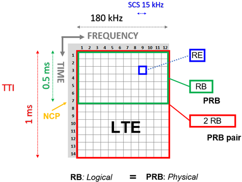
In summary, in the case of LTE (SCS 15 KHz and Normal CP) we have:
- 12 SC, 7 OFDMA Symbol = 1 RB or 1 PRB
- 12 SC, 14 OFDMA Symbol = 1 SB (Scheduling Block) → smaller block to give to a user
The correct design of the PRB is important because it ensures the quality user experience, in addition to of course minimizing the necessary investments.
That’s why it is so important that all the concepts we have seen today are fully understood!
And one last concept we’ve seen quickly above - but we’ll see with much more detail some other day - is the “Scheduler”.
We can say with no doubt that the Scheduler is the center of communications in systems such as LTE and 5G NR. Pretty much everything depends on the scheduler settings, as it is the Scheduler that in the end will tell you how much a user requires in terms of data to be scheduled to be transmitted. The Scheduler schedules the PRBs! ![]()
Subcarrier Spacing (SCS)
We’re almost finish for today. Let’s one talk about a term we used a lot in the above examples: spacing between subcarriers. As this is an important term, and it is also widely used, we refer to the spacing between subcarriers as SCS (Subcarrier Spacing).
And also we’ve seen that in LTE we have only one type of SCS (Subcarrier Spacing) - of 15 kHz. In 5G NR we have several possible types of SCS (Subcarrier Spacing), and this is one of the main differences between LTE and 5G NR - and implies differences in so-called Numerology - which is defined by SCS (Subcarrier Spacing) and CP (Cyclic Prefix). But also another thing to explore in some next tutorial.
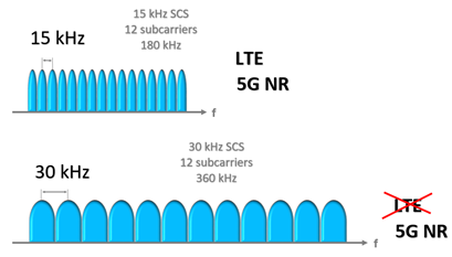
It is worth noting here that as the LTE is limited to a 15 kHz SCS, so it is only possible to send a maximum of 14 symbols per millisecond.
In 5G NR the SCS is flexible (it is no longer fixed at only 15 kHz), and with this we manage to increase the number of symbols in a slot simply increasing the Spacing between subcarriers (SCS).
Forexample, in the 5G NR we can double the amount of data in a slot using carrier spacing to 30 KHz.
If we continue to increase the SCS (up to the set maximum of 240 kHz for millimeter waves) we can compress even more symbols.
And you know the great advantage of that possibility? All this increase implies in improved Latency and Throughput! But of course it will depend on the amount of Spectrum available (much larger bands needed), and we should also have mechanisms to compensate for the worst channel conditions at higher frequencies.
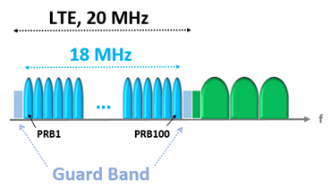
Guard Band
Just as in the time domain we have the CP to avoid interference, in the frequency domain we have the Guard Band.
The Guard Band is a narrow frequency band that separate two wider frequency bands in order to avoid interference that would result in degraded transmission quality.
In LTE for example, the guard band is 10% of the available bandwidth.
This explains for example why we have 100 PRB at a bandwidth of 20 MHz (not 111.11 PRB).
If it wasn’t for the guard band, we’d have:
- 1 PRB (in frequency domain) = 12 subcarriers
- 1 subcarrier = 15 kHz
- 12 subcarriers = 180 kHz
- Bandwidth = 20 MHz = 20,000 kHz
- 20,000 / 180 = 111.111 PRB
Considering the guard band:
- 10% = 2.000 kHz
- And the rest is 18,000 kHz
- So: 18,000/180 = 100 PRB
Note: the 10% LTE Guard Band just doesn’t apply to 1.4 MHz bandwidth (where we have 6 PRBs).
In summary, not all subcarriers of a bandwidth are used and some subcarriers act as guard carriers at the edges.
FDD-TDD, Downlink-Uplink
All the logic seen above applies to Frequency Division Duplex (FDD) communications. For TDD systems of course, the frames structures are different, since we have different requirements for segregating the transmitted data.
However, the reasoning is the same, and can be easily applied.
For example, in LTE FDD systems we find the above explanations for Type 1 frame structure, and for LTE TDD systems we have Type 2 frames.
There are also similar considerations for Downlink / Uplink.
In Downlink the least amount of resources we can identify is called RE (Resource Element). In Uplink it is called the Resource Unit (RU) - similar to the Resource Block (RB) in Downlink. In the case of LTE (where 12 subcarriers using a spacing of 15 kHz are allocated) the RU corresponds to the PRB pair.
But of course, we will not extend further into this and other topics - everything will be explained as easily as possible in the next articles, as we have already highlighted some possible subjects.
Conclusion
This was our tutorial to explain how communication occurs on systems like LTE and 5G NR through real life example.
The main concepts we hope have become clearer today are:
- RE (Resouce Element)
- RB (Resource Block)
- PRB (Physical Resource Block)
- CP (Cyclic Prefix)
- Symbol Length
- Slot
- Subframe
- Frame
- SCS (SubCarrier Spacing)
- Guard Band
If you were able to understand how information was entered and associated with the time and frequency domains, then you understood in a simplified way how LTE and 5G NR works!
I hope you enjoyed it.
See you in the next tutorial - leave below your comment. ![]()