Introduction
When we think about communication in a telecommunications system, the first thing that comes to mind is someone talking to another person.
Although it may seem simple, the transmission and reception of information is quite complex, considering the many possibilities and scenarios where this may occur.
And one of the main schemes is involved in the modulation. So try to understand what it is today.
Note: Our goal here is to be as simple and straightforward as possible. For example, do not reach the level of demonstration of theorems such as Nyquist and Shannon - involved in the issue. This reading, however it is recommended further or if you have more interest in the subject. Anyway, try to pass the ideas and concepts. Later, you can extend your studies, if any, so much clearer.
What is Modulation?
Let’s start with the basic function of any communication system, transmitting information from one location to another.
Speaking simply so, it seems a simple process … but it is not!
To try to identify the many concepts and processes involved, let us consider a communication between two people.
If these people are close, one speaks and another listens.

We already can observe some basic concepts.
-
The information power where the sound of the voice, is given by the capacity of the lungs of each which can whisper, talk or sream.
-
The transmission medium this information is the air or free space.
-
Who speaks is the transmitter , and who is listening is the receiver .
If these people are far away, then the communication needs other means, such as a telephone line or a radio channel frequency.

Note that now we introduce new digital devices, besides other techniques to allow the original data - in this case the voice - is crafted so as to reach the other person.
The information coming out of the transmitter needs to be changed (modulated) to then be transmitted. At the receiver, must do the reverse process, or the demodulation of the information, converting the same to the original information.

More concepts …
-
Modulation : changing the characteristics of the signal being transmitted.
-
Demodulation , the reverse process of modulation.
So far so good? So let’s continue …
Our voice, as well as most of the sounds found in nature, is analog. Until there are purely analog transmitters, such as the transmission of AM and FM. But let us not worry about it, almost everything today is even digital.
Before our voice to be transmitted, it must be converted. For this, there are digital devices that convert analog voice through a process of sampling and quantization.
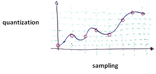
The analog signal is first sampled first, then quantified into levels. Each of these levels is then converted to a binary number.
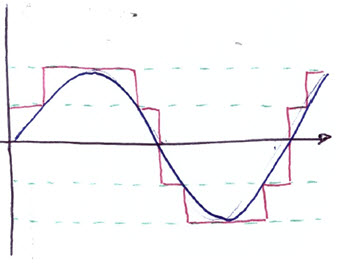
Below, we see an analog signal (blue) with its equivalent digital signal (red). Using only two levels, we have:
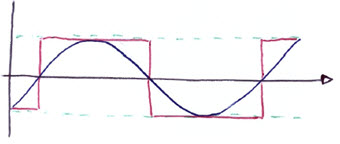
If we use 4 leves, we have the following:
A specific type of modulation, PCM - Pulse Code Modulation is the method used to convert the voice signal into digital signal, and generally used in telephony. Between the maximum amplitude and minimum signal levels are set 16 (0 to 15), and these are encoded as binary numbers (0000, 0001, …, 1111).
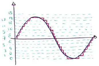
For our voice is considered an effective bandwidth - lower limits 300 Hz, and upper limit between 3500 and 4000 Hz. Sampling rate is 8000 / s.
We have a stream of 64 Kb / s: 8000 samples x 1 byte = 64.000 bits / second (64 kbps).
Okay, at this point we have then the signal of our voice digitally represented by binary numbers.
Now let’s see how the other digital modulation techniques?
Digital modulation has advantages over analog. For example, it is much easier to recover the signal, because we avoid the accumulation of noise and distortion - compared to the analog modulation. (In cases of various modulations/remodulations).
Furthermore, the streams of digital bits are much more suitable for various multiplexing schemes.
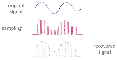
But while the benefits are large, digital modulation also has its disadvantages. The main one is that it requires more bandwidth than analog methods.
And then come the techniques developed to minimize this problem.
-
The digital signal compression : to reduce the number of bits needed to carry the same information.
-
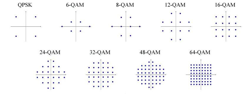
The use of advanced modulation techniques : increasing the number of bits carried by Hertz or bandwidth - QPSK, OQPSK, GMSK, etc …
So let’s talk a little about these modulation techniques.
First, let’s get used to the characteristics of modulation (change) of the RF signal. It can be basically of three types:
-
Frequency
-
Amplitude
-
Phase
The following figure helps to understand this, where we see a reference signal - the first - and their corresponding modulations altering the frequency (1), amplitude (2) and phase (3).
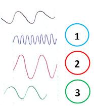
All of these techniques alter a parameter in the sine signal somehow representing the information we have.
Let us now make one more little analogy that will help us establish the concepts of modulation.
Imagine a person, a night in an apartment like the one shown below, with two windows. Suppose further that this person wants to communicate with his girlfriend, far away.
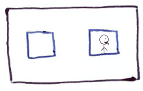
This person has combined with his girlfriend that he turn the light on the right, it means 1. If he turn the light on the left, means 0.
We say that this signal then has 1 dimension, because the person uses only one dimension (goes from one side to another) to indicate a change of symbol.
When it glows, we have a symbol. (Since we have two windows, we have two symbols. In this case a symbol represents a bit).
Congratulations, you just know a modulation technique for the first phase: BPSK!
BPSK
BPSK means Binary Phase Shift Keying modulation.
This modulation uses a sinusoidal signal and varies its frequency to transmit information. In our example, turning on the light from every window.
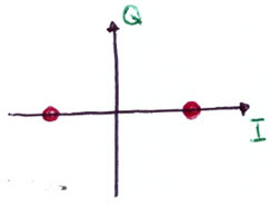
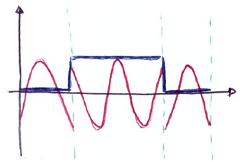
Each symbol is indicated by the change of position. In BPSK, is signaled by changing the phase of sinusoidal signal, a phase of 0 and one with 180 degrees.
So, could you understand?
Bringing the xy axis, the BPSK signal will have only the x-axis. Given our signal as a vector, it is like it switches back and forth that axis.
Indeed, the axis here is no longer called xy, but IQ. The letter I means a carrier ‘In Phase’ with the carrier signal. And in the letter Q means ‘Quadrature’ (or perpendicular). Then we have the figure below represents the BPSK modulation.
As an example, see how it is transmitted at 0110 bits sequence using BPSK modulation. Note: For demonstration purposes, we use a frequency of 1 Hz, where it is easy to see the variations. Actually, this frequency is much higher, but would expose what we want.
QPSK
Now let’s return to the example of lovers.
Suppose now the boyfriend has moved to a different apartment, as shown below.
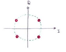
Now, see that he combined a new code for each lamp was lit. In other words, each symbol carries two bits. For example, if it light up right on the top floor means 11 .
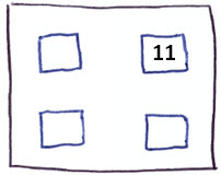
You’ve probably made the analogy with the xy axis, or rather IQ:
OQPSK
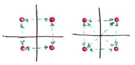
Offset QPSK is a variation of QPSK, where only one channel I or Q can vary by time. The goal is to offer better performance in some applications, with a lower rate of bit errors. The signal is more 'friendly’to the transmitter.
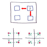
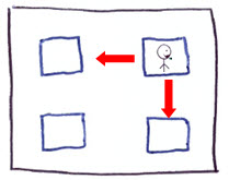
In the case of lovers, the boy who was in the right window of the upstairs could only go down or sideways.
In the diagram below you can see the possibilities of transition of OQPSK and QPSK.
FSK
In FSK - Frequency Shift Keying, signal carrier always has the same amplitude, and never suffers from discontinuous phase changes. That signal is switched between two frequencies, according to the value of the bits.
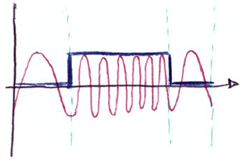
This type of signal is called envelope-constant, and suffers less distortion in applications with high-power amplifiers.
MSK
Minimal Shift Keying is a particular type of FSK, in which the deviation of the peak frequency is equal to half the bit rate.
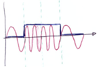
This minimum frequency separation allows the detection of two orthogonal binary states.
This type of modulation has many advantages. It has an improved spectral efficiency, compared to other PSK modulation schemes. It’s kind of envelope-constant - as we speak, and suffers less distortion in applications with high-power amplifiers. For mobile phones, this contributed to a lower consumption of battery - good thing, isn’t it?
GMSK
GSMK is basically the MSK signal applied to a Gaussian filter, which reduces the speed of the rapid transitions of frequencies, which ended before spreading the energy in adjacent channels. With this spectrum modulation turns out to be even smaller.
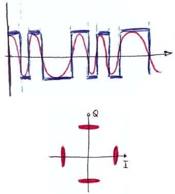
Well, we only show some of the existing modulation schemes. Anyway, these are the key, and our initial objective - the concept of modulation - has been shown.
Other Modulation Schemes
Although complex modulation schemes are able to encapsulate large amounts of data in a relatively small bandwidth, they are much more vulnerable to noise and distortion during transmission.
Other important modulation schemes are:
-
π/4 DQPSK
-
8PSK (it’s like 2 x QPSK - 000 … 111)
-
16 QAM
-
64 QAM
A more detailed explanation of these types is then for another opportunity, because until now we have extended too much for today.
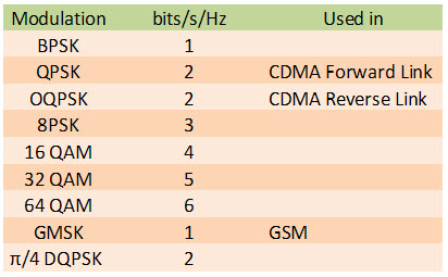
Finally, here is a table with some comparisons of modulation schemes.
Conclusion
This was a brief explanation of modulation scheme used to change the characteristics of the signal being transmitted, allowing for greater efficiency in this process.
We explained the basic concepts, and know some of the main types of modulation, particularly those used in Telecom and IT.