Hold on, this report MAC LL1 you provided all reports are aperiodic and there are 3 records. 2 for CSI-RS and one for SSB.
Which one is used for beam switching?
Yes, that’s what I said it doesnt give info about beam switching.
But @samohiuddin have maybe some other msg which gives this info…
This message shows the info which @Jaeku_Ryu explained:
Wow first time I saw this msg  .
.
Well… there are so many occurences of trs-info and repetition in your example?
How can we decide which one is the good one for beam switching?
May be it have something from L1 on the best beam selection as @samohiuddin quoted.
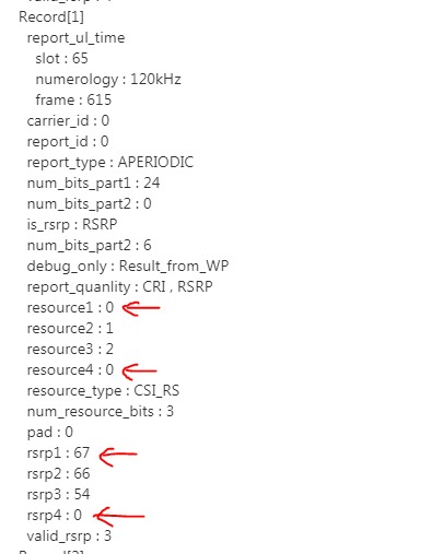
Also I don’t understand in the MAC LL1 report example how can CSI-RS beam number 0 have 2 different rsrp values: 67 and 0 like in the snapshot?
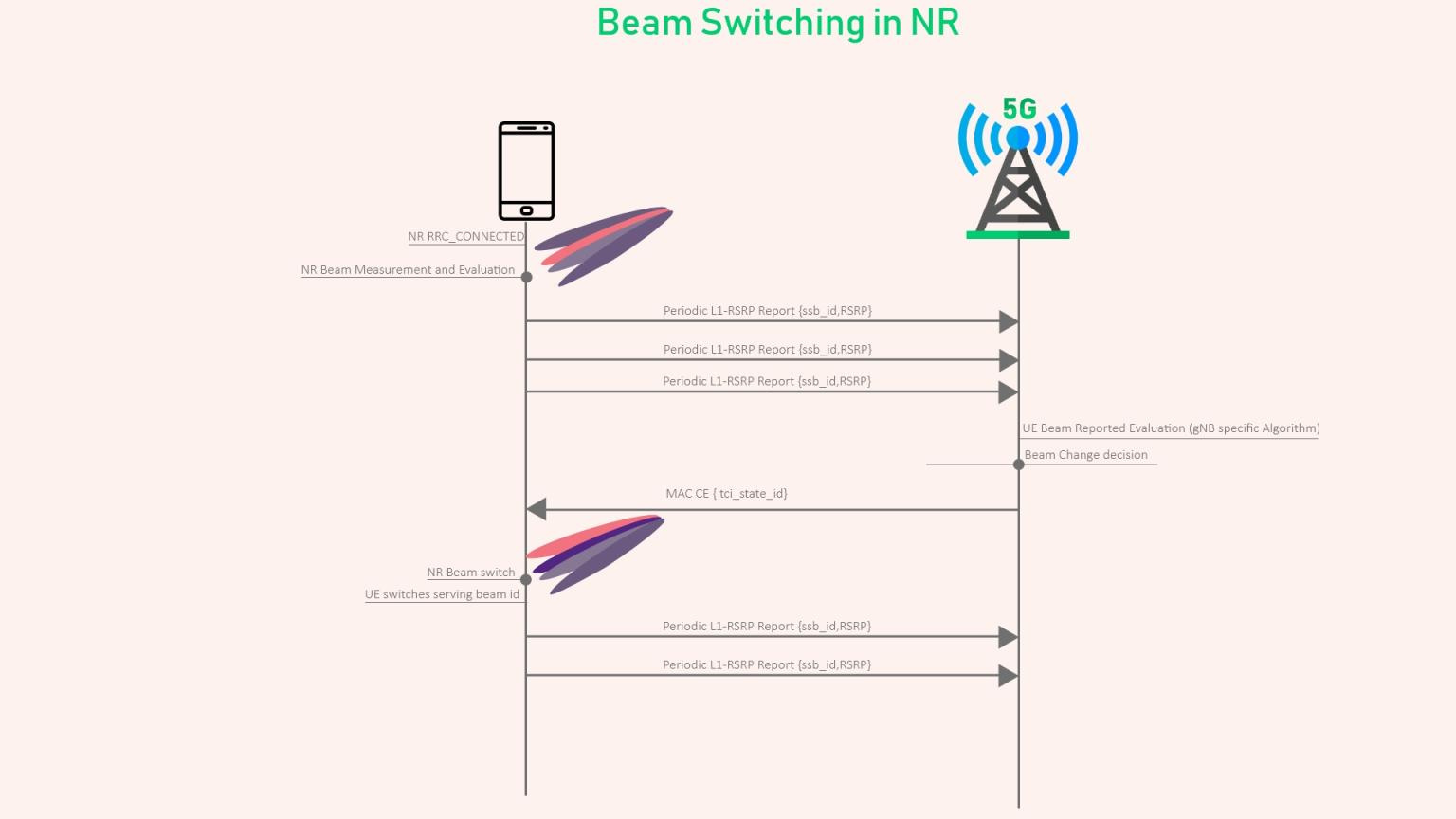
How Beam Switching Happens in NR?
Below Image provides an High level view of how Beam switch works in NR, The process is very complicated and understanding the entire process will require quite a effort.
Here is the top down overview
-
UE Sends SSBRI report periodically containing information regarding the best beams to gNB based on the parameters configured in RRC Reconfiguration.
-
UE can report up-to 4 SSB beams with its corresponding RSRP.
-
gNB receives the L1-RSRP periodic reports and evaluates multiple reports before switching the beam( How gNB decides when and which beam to switch depends on gNB Algorithm)
-
Once decision is made to switch the beam by gNB, it sends MAC CE with tci_state_id which maps to the SSB beam id on which UE need to switch.
-
UE checks the tci_state_id from RRC Reconfiguration message and switches the beam.
-
UE starts the process again by reporting periodic L1-RSRP reports for best beams.
How this happens when tci-presentinDCI is missing?
This is the triggering message to switch the beam.
.pdsch-Config:- setup
- . . . . . . . . . . . . . . . . . . . . . . . . . . . .dmrs-DownlinkForPDSCH-MappingTypeA:- setup
- . . . . . . . . . . . . . . . . . . . . . . . . . . . . . .dmrs-AdditionalPosition: 1 ( pos1)
- . . . . . . . . . . . . . . . . . . . . . . . . . . . .tci-StatesToAddModList [ 0 ]
- . . . . . . . . . . . . . . . . . . . . . . . . . . . . .tci-StateId: 0
- . . . . . . . . . . . . . . . . . . . . . . . . . . . . .qcl-Type1
- . . . . . . . . . . . . . . . . . . . . . . . . . . . . . .bwp-Id: 1
- . . . . . . . . . . . . . . . . . . . . . . . . . . . . . .referenceSignal:- csi-rs: 2
- . . . . . . . . . . . . . . . . . . . . . . . . . . . . . .qcl-Type: 0 ( typeA)
- . . . . . . . . . . . . . . . . . . . . . . . . . . . .tci-StatesToAddModList [ 1 ]
- . . . . . . . . . . . . . . . . . . . . . . . . . . . . .tci-StateId: 1
- . . . . . . . . . . . . . . . . . . . . . . . . . . . . .qcl-Type1
- . . . . . . . . . . . . . . . . . . . . . . . . . . . . . .bwp-Id: 1
- . . . . . . . . . . . . . . . . . . . . . . . . . . . . . .referenceSignal:- ssb: 0
- . . . . . . . . . . . . . . . . . . . . . . . . . . . . . .qcl-Type: 2 ( typeC)
- . . . . . . . . . . . . . . . . . . . . . . . . . . . .resourceAllocation: 0 ( resourceAllocationType0)
- . . . . . . . . . . . . . . . . . . . . . . . . . . . .rbg-Size: 0 ( config1)
- . . . . . . . . . . . . . . . . . . . . . . . . . . . .maxNrofCodeWordsScheduledByDCI: 0 ( n1)
- . . . . . . . . . . . . . . . . . . . . . . . . . . . .prb-BundlingType:- staticBundling
- . . . . . . . . . . . . . . . . . . . . . . . . . . . . . .bundleSize: 0 ( n4)
Here it is showing reference signal csi-rs for tci state 0
ssb for tci state 1
For beam switching it needs qcl type D.
Other type of qcl like A, B and C are not for beam switching.
QCL type D valid for FR2 (>6 Ghz).
If I’m not wrong.
Where did you get this info that type D is valid just for FR2?
QCL Type - Assumptions
Type A - Doppler shift, Doppler Spread, Average Delay, Delay Spread
Type B - Doppler shift, Doppler spread
Type C - Average delay, Doppler Shift
Type D - Spatial Rx
The QCL types A, B and C are applicable for both below and above 6GHz transmission, but the spatial QCL Type D is applicable only in higher carriers where the UE is essentially forming beams.
Just realized this if this mmWave log.
@RFSpecialist, from the last msg shows valid rsrp only 3.
So the last one 0 is invalid means only 3 rsrp reported here.
Ok thanks, it makes sense.
But why we have 3 reports and not just one.
Which one among those 3 it is used for beam switching?
Okay so we have 2 TCIs, so which one will be used for the switching?
QCL type D is the only one that gives quasi collocation for PDSCH with CSI-RS beams or with ssb beams.
All the rest are used for something else like doppler shift,average delay, etc.
@ankgitm, is this the parameter that decides whether beam switching is done on ssb or on csi-rs? Please be more specific.
Yes as per my knowledge what I learn.
Why we are saying TRS true indicates SSB based switching?
TRS =Tracking reference signal how it linked with it?
As mentioned above.
This is what is explained on ShareTechNote.
It is not just trs info.
It is trs info and repetition; combination of those 2 params decides which beam is used for beam switching.
We have still to clarify how beam is switched by UE when tci-presentinDCI is missing.
How UE knows when to switch to the new beam without TCI in DCI?