Download Slide
Beamforming.pptx (121.3 KB)
Beamforming.xlsb (91.7 KB)
Slide Notes
When the frequency spectrum is limited, we need to look for ways to improve its efficiency.
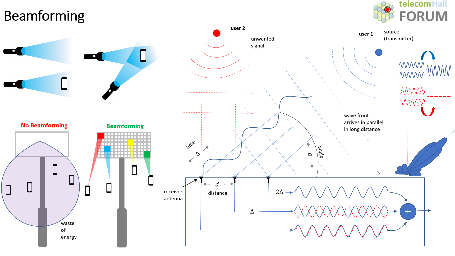
And without a doubt, one of the most fantastic techniques is beamforming, as it manages to adapt the radiation pattern of a set of antennas, making sure that the coverage, the energy is directed only where it is necessary.
As it is always easier to understand complex concepts through analogies, let’s associate the coverage of an antenna (its energy lobe) with the light coming from a flashlight.
This light can be pointed towards a user. But it may be, for example, that it is far away, and its light (coverage) is weak.
One way to increase light at that user is to point another beam, from another antenna, in that direction.
That is, with 2 flashlights pointed at the same user, we have more efficiency!
But now let’s bring the analogy to the real world of mobile communication. How can we “point” the antenna beams according to our needs?
Let’s see this through a demonstration.
The best way to see it is through the PowerPoint file animation (slide) that you can download and edit as you wish.
Let’s think about it from the point of view of a user (user 1) transmitting.
The signal it transmits - the wave front - arrives at the antennas practically in parallel. (Let’s assume it’s quite far from the receiver)
Continuing, imagine an antenna receiving this signal, which arrives at this antenna with a certain angle (a).
That signal is measured, and processed in an electronic circuit.
So far, nothing new.
But now imagine a second antenna, separated by a distance (d) from the first. The signal will arrive at that antenna with a time delay (∆).
This is where the great magic happens: knowing this delay, we can adjust so that the signal is also forwarded in the same way, in our combiner. And so, we will have the sum of the 2 signs!
But let’s continue… suppose for example another signal, now from another user (user 2). In red in our image. And this is an unwanted user.
In our example, this user’s signal arrives at both antennas without any delay. In the first antenna, the signal will go normally. Also on the second one - only a delay will be applied to it! And that will cause it to be cancelled! In other words, we eliminate the interference of the other unwanted user.
To conclude, let’s imagine more antennas… a third.
That third antenna receives the signal, meaning we’re collecting even more power - which is always good, especially on weak signals and with a lot of noise. And in the same way, with the processing of angle, distance, delay… it adds to the signal, making it stronger and more targeted.
In summary: if we know all the variables (angle at which each signal arrives, distance between the elements of collector antennas, corresponding delays, etc.) we can make the necessary adjustments in the summation of the signals, and thus the resulting signal will be exactly as we wish.
Of course, our analogy, and example, were very simple - but they give a very interesting idea of the whole process.
And now when you hear about beamforming you will already have a good understanding of how this is possible.