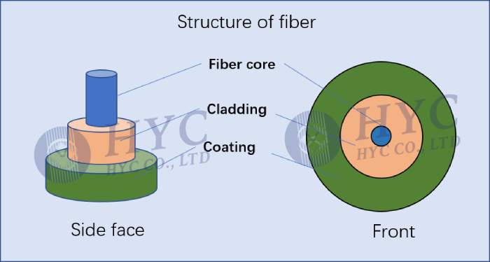
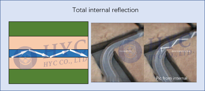
First, let’s understand how optical fibers transmit signals. The structure diagram of fiber generally consists the core, cladding, and coating. The fiber core and cladding are made of glasses with different refractive indices. The core is where light travels, which made of high refractive index silica glass and is the only part of the cable that includes a rare-earth element. The cladding is the material that surrounds the core, which made of lower refractive index silica glass. When light hits the cladding, it bounces back into the core. Light is injected into the fiber at a specific incident angle, and total internal reflection then takes place at the boundary between the core and the cladding because the cladding has a lower refractive index than the core. Without the cladding, light would go in all directions and exit the core. But thanks to the cladding’s refractive index, light remains in the core and continues its path.
Signal loss always occur during fiber transmission. In telecommunications, return loss is the loss of signal power due to signal reflection or return by a discontinuity in a fiber optic link or transmission line. Generally speaking, return loss is the result of back reflections. It is usually expressed as a ratio in decibels (dB). The result is always a positive number, and a higher value is better. Typical optical return loss ranges between -15dB and -60 dB .
Causes of return loss in optical fiber systems usually has: caused by dirty connector end faces; the height of the fiber is controlled at +/-20nm, which can get a better return loss value; can be caused by core misalignments and air gaps; caused by poorly polished end faces. Micro and macro bends in the fiber that can occur as a result of installation stresses, such as exceeding bend radius or pulling tension requirements, can also affect return loss. In order the make sure precise alignment of two fibers to get high return loss, the ferrule end faces of fiber optic jumpers are usually polished by different angles. The angle of a connector end face can also have an impact on return loss.
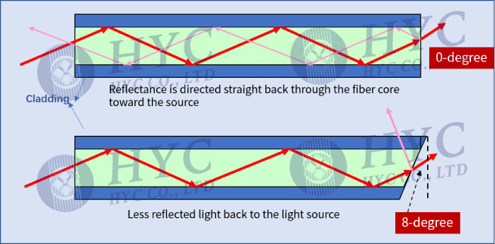
When two flat end face of connectors mate, reflectance is directed straight back through the fiber core toward the source. Return loss can reach -50dB or lower. However, the angled end face of connector causes much of the reflected light to angle into and be absorbed by the cladding that surrounds the fiber core, which causes less reflected light back to the light source. Proven by rich experience and experimental verification, an angle of 8-degree is the best. An angled connector is typically -65dB or lower.
According to different end face angles, there are three types of optical fiber end face polishing methods: PC, UPC, and APC. The typically return loss of PC, UPC and APC connectors is 40dB, 55dB and 65dB respectively.
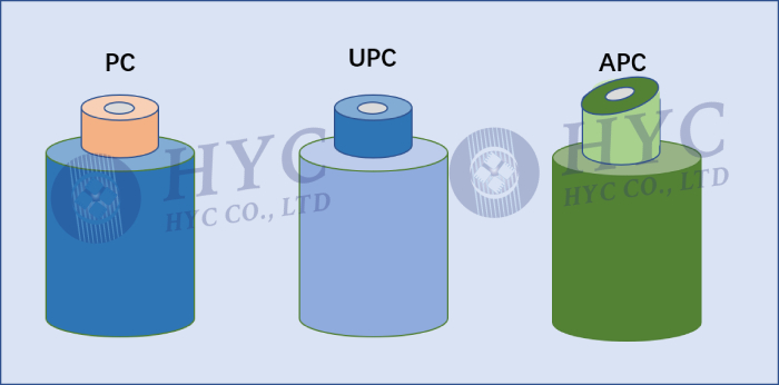
PC (Physical Contact). The two end faces are polished to be slightly curved or micro spherical, and the fiber core is at the highest point of the bending. This eliminates the air gap and forces the fibers into physical contact.
UPC (Ultra Physical Contact) is based on the PC to optimize the end face polishing and surface finish, the end face looks more dome-shaped. The end face of the UPC connector is not entirely flat, and there is a slight arc to achieve more accurate connecting.
APC (Angled Physical Contact). The end face of APC is usually polishing into an 8-degree angle. The 8° angled bevel makes the fiber end face tighter and reflects light through its beveled angle to the cladding instead of returning directly to the source, providing better connection performance.
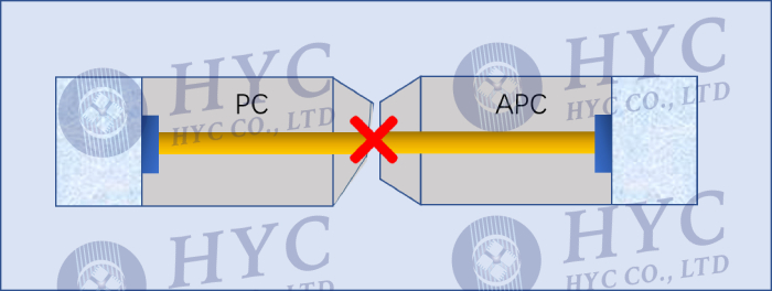
Connector connections need to be in the same end face structure; for example, APC and UPC cannot be mated together, because doing so will resulting in poor connector performance. However, the end faces of PC and UPC fibers are flat, and the difference is in the quality of grinding. Therefore, the mixed connection of PC and UPC will not cause permanent physical damage to the connector. The APC fiber optic connector is usually green. UPC/PC connectors are easily identified by their blue color on the connector boot.
PC is the most common grinding method for optical fiber connectors, which is widely used in telecommunication operator equipment. UPC is commonly used in Ethernet network equipment (such as ODF fiber distribution frames, media converters and fiber switches, etc.), digital, cable television and telephone systems. APC is generally used in optical radio frequency applications such as CATV, and in passive optical applications, such as PON network structures or passive optical local area networks.