A phased array is usually explained as a system that controls phase across many antenna elements to steer a beam. In theory, if the progressive phase shift is correct, the main beam points toward the desired scan angle but this explanation is incomplete. Beam steering is a mathematical phase condition while useful radiation depends on the full electromagnetic behavior of the array. The beam can be commanded correctly, yet the array may still radiate very little power in that direction.
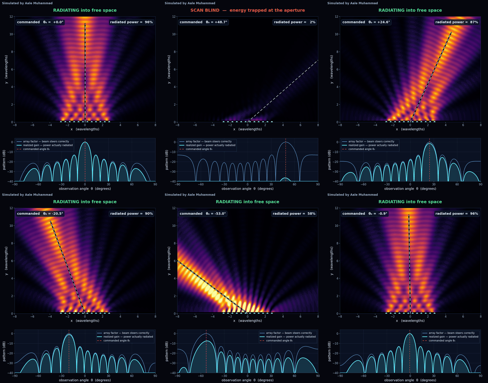
This problem is often linked to scan blindness. As the beam scans away from broadside, each element no longer behaves like an isolated antenna. Mutual coupling, embedded element pattern distortion, surface wave excitation, active impedance variation and finite ground plane effects all become stronger. At certain scan angles or frequencies, the array can couple energy into non-radiating or poorly radiating modes instead of launching it into free space. The result is severe gain loss, high active reflection, pattern collapse or a deep null near the intended scan direction.
This is why phased array design cannot rely only on ideal array factor plots. The array factor may show the beam steering correctly but the embedded element pattern may be weak, the active impedance may be badly mismatched, or scan loss may destroy the link margin. In radar, satellite communication, 5G/6G beamforming and electronic warfare systems, this can mean reduced detection range, unstable link quality, poor angular coverage or unexpected blind zones. A real phased array must be evaluated as a coupled electromagnetic aperture, not just a set of phase shifted point sources.
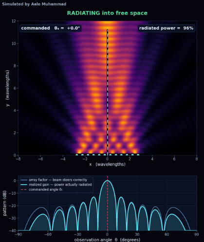
Critical Formulas:
a) Progressive phase shift
→ Δφ = −(2πd/λ)sinθ₀
Δφ = phase shift between elements, d = element spacing, λ = wavelength, θ₀ = desired scan angle
b) Array factor
→ AF(θ) = Σ wₙeʲⁿᵏᵈˢⁱⁿθ
AF = array factor, wₙ = complex element weight, k = 2π/λ, d = spacing, θ = observation angle
c) Active reflection coefficient
→ Γ_active,n = Σ Sₙₘaₘ / aₙ
Γ_active,n = active reflection coefficient of nth element, Sₙₘ = coupling between elements, aₘ = excitation wave at mth element
d) Scan loss approximation
→ G_scan ≈ G₀cosθ₀
G_scan = scanned gain, G₀ = broadside gain, θ₀ = scan angle
- A phased array can apply the correct steering phase but still lose gain due to active impedance mismatch
- Mutual coupling can change the embedded element pattern and create weak radiation at certain scan angles
- Surface waves or substrate modes can trap power instead of allowing it to radiate into the desired beam
- Wide angle scanning may produce blind zones where the array factor looks acceptable but realized gain collapses
A phased array does not only need to point correctly, it must also radiate correctly after the entire aperture starts interacting.
LinkedIn: 