Hi Experts.
Anybody knows when P0Nompucch is used by UE?
When handset become ON? Or every time pucch channel send by handset?
Hi Experts.
Anybody knows when P0Nompucch is used by UE?
When handset become ON? Or every time pucch channel send by handset?
Power calculations are different for each case and changes based on the channel.
So, p0nominalPucch is used only when calculating the power for a Pucch transmission
There is a feature for close loop power control, and my question is that this item calculate all the time that pucch send or just in the time when power of UE is ON?
Recommended complementary reding here:
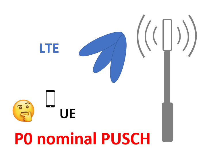
P0 nominal PUSCH is a single parameter that is set for each LTE cell (a cell being a sector). It is the target power level that the LTE eNB (e Node B, i.e. base station transceiver) receiver wants to receive per resource block (RB, or each 180kHz of spectrum). In open loop power control, the UE uses downlink Reference Signal (RS) measurements to approximately determine the RF path loss, and uses this information along with P0 to determine the ideal power to transmit over PUSCH (this occurs only briefly in closed loop is supported). In closed loop power control (occurs most of the time), the eNB receive power measurements per UE and per RB, are used by the eNB to command TPC (transmit power control) commands over the downlink control channel to the UE (PDCCH). This closed loop power control commands the UE to increase or decrease its power in 1dB or 3dB steps at a slow rate, and is designed to overcome slow fading in the RF channel. The eNB is aware of when the UE is near or at full power by means of the UE transmit power headroom reports sent in PUCCH (uplink control channel).
P0 is a design/optimization parameter that balances a trade-off between maximum UE uplink throughput and overall cell capacity. With a high P0, a close-in UE with very low RF path loss can achieve very high throughputs per RB because it achieves very high SINR (signal to interference plus noise) levels per RB. Similary UE’s who can achieve P0 target will transmit at higher power spectral density (PSD, or power per RB). However the trade-off is this higher PSD creates more co-channel interference for adjacent cells, with the overall result of lower overall system maximum UL (UpLink) capacity. Vice-versa, with low P0 setting, the maximum UE throughput in very low RF path loss conditions is not nearly as high because it is more noise limited (does not achieve as high SINR per RB); however the advantage here is much less co-channel interference to adjacent cells. P0 has no impact on UE’s at cell edge because they are at minimum # of RB’s and maximum power anyway (i.e. they are just ‘hanging on for dear life’) , at least for Macro cells.
Adjusting P0 is a balancing act done on a system wide level to balance max UL throughput (in excellent conditions) and total system UL capacity. I have used an RF modeling tool for years called Planet to simulate and model the UL traffic capacity, which takes into account P0 and the specific RF design (tower locations, antenna heights, etc. etc.), and the trade-off can be very dramatic with at least a two times change in UL capacity between the two extreme settings of P0. The default level for P0 nominal PUSCH for one manufacturer, if I recall correctly, is around -102dBm (this is per RB). The noise floor per RB for 2dB noise figure is approx -118dBm.
Note that there is also a power target level for PUCCH, called P0 nominal PUCCH with similar behaviour. Default level for P0 for PUCCH is much lower than for PUSCH because it is a much more robust channel with low bit rate requirements.
The UE reads important radio resource configurations in the SIB-2 block.
SIB-2 also contains uplink shared channel (PUSCH) and physical channel (PUCCH)configurations.
Among other parameters, it also includes the following -
P0 Nominal PUSCH, which determines the derivation of PUSCH transmit power and P0 Nominal PUCCH, which determines the calculation of PUCCH transmit power.
This parameter p0pucchNominal is part of open loop power in the equation.
That means, this has effect on pucch power all the time.
P0 is signaled via BCCH in SIB 2 all the time.
How about close loop power control?
This is used when the Power Control is in place.
You have independent power control algos for PUCCH and PUSCH.
Ok thank you all 
What about in case of Handover from LTE Cell1 to Cell2? If it doesn’t come in RRCReconfig
Effect of P0 (P Zero) setting on the performance of the eNB connected to this low power active DAS vs. passive DAS?
Please provide examples to illustrate if applicable
In active DAS, you cover bigger area so you have more cell edge users, but when UE at cell edge most probably already reached the max power in UL so changing p0 will not affect cell edge users.
In passive DAS, I assume the coverage is much smaller than setting p0 will directly impact the user throughput in UL near base station.
Great discussion and recommended site. thanks