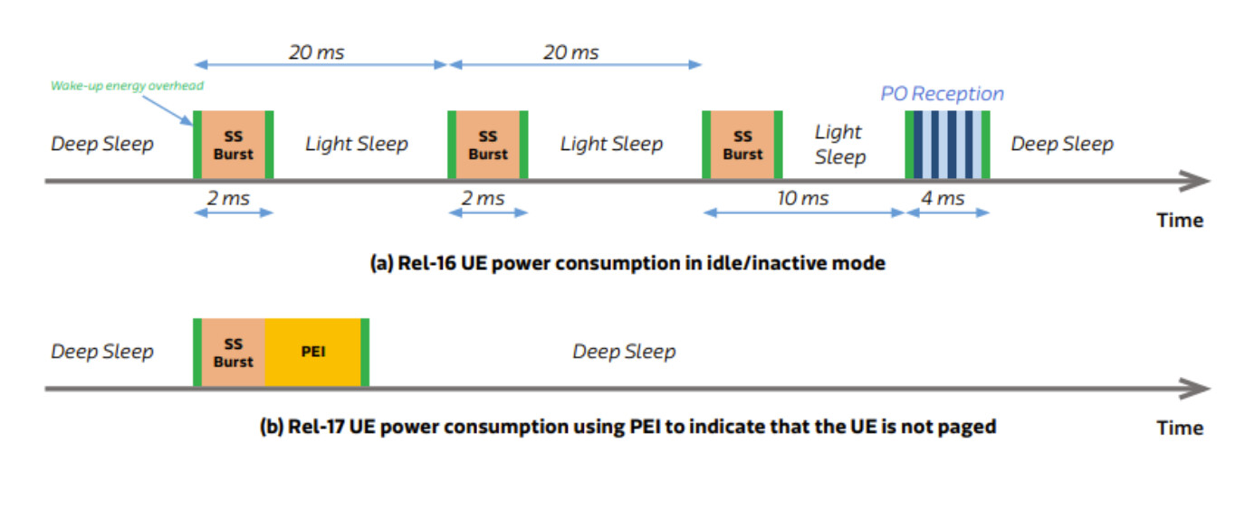
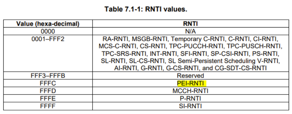
Paging Early Indication (PEI) is to improve the UE power saving in idle and inactive modes introduced in 3gpp-R17.
PEI can avoid unnecessary PO reception by indicating to UE whether to decode paging (PDCCH/PDSCH) in its Paging Occasion.
Therefore, UE can skip the time-frequency synchronizationprior to a Paging Occasion(PO), if the UE need not to monitor the PO.
The PEI can be signaled via a Downlink Control Information (DCI) message carried in the Physical Downlink Control Channel or via a Reference Signal, e.g. the Secondary Synchronization Signal.
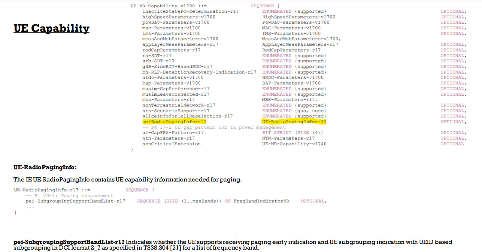
PEI may carry sub-grouping information to divide the UEs, sharing the same Paging Occasion, intosub-groups. This results in lower group paging rate and fewer false paging alarms.
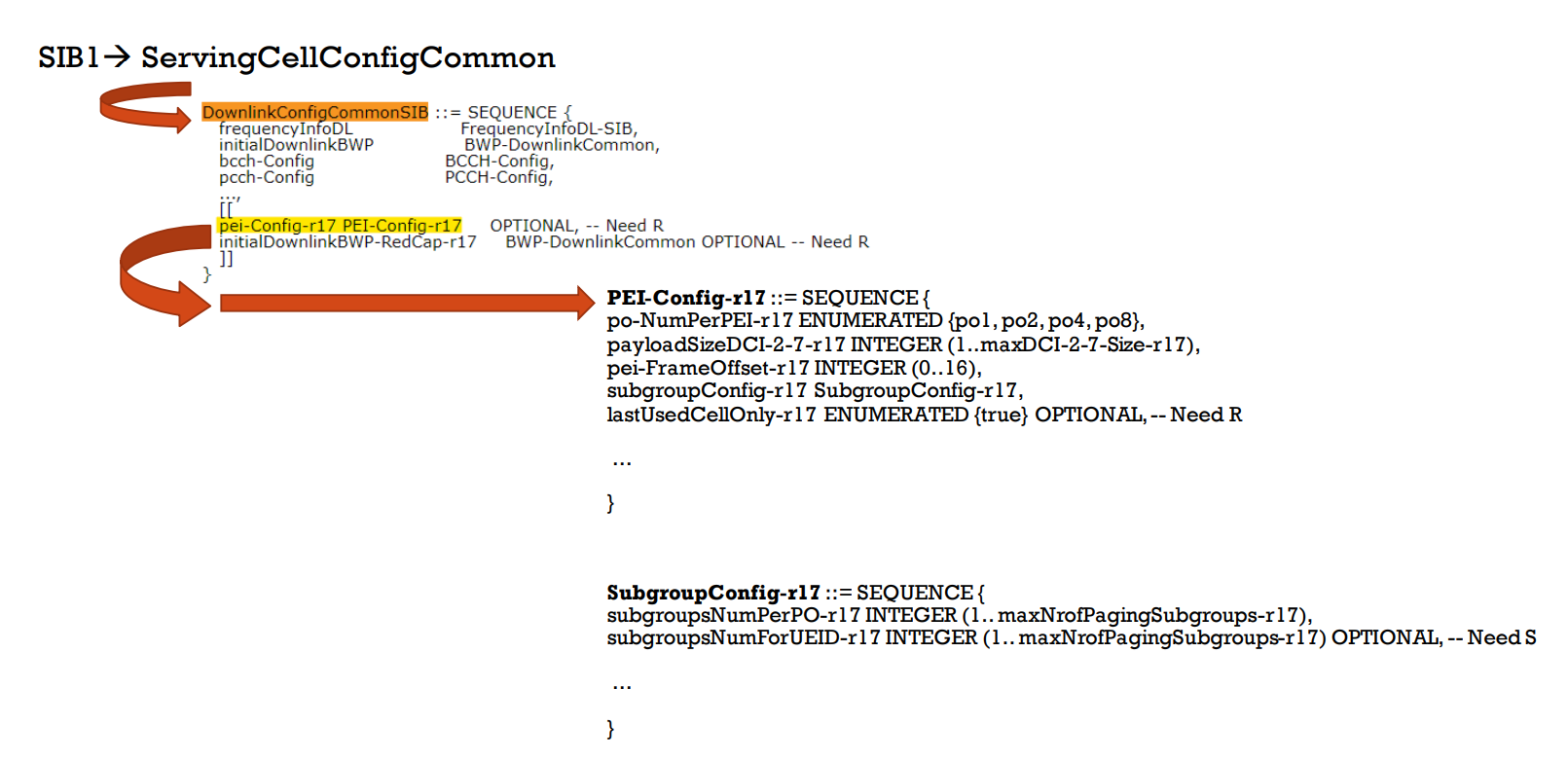
SIB1 is used to inform UE about PEI config as PEI-config IE.
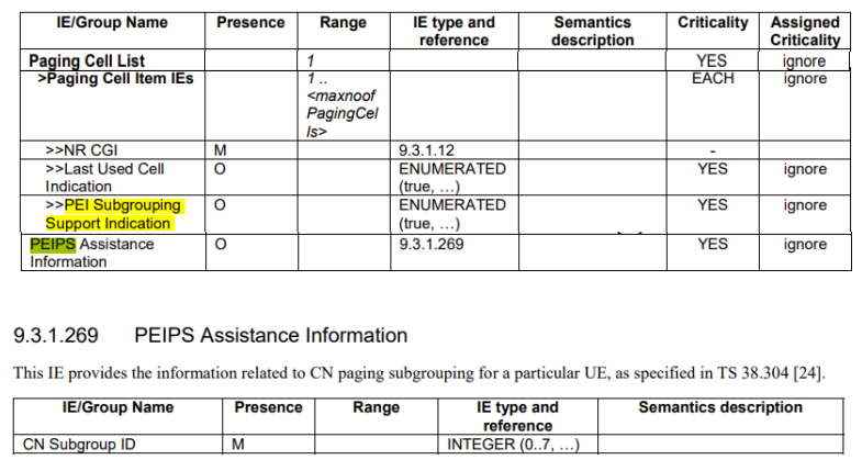
The PEIPS(Paging Early Indication with Paging Subgrouping) Assistance Information IE may be included in the PAGING message, and if present the gNB-DU shall, if supported, use it for paging subgrouping of the UE, as specified in TS 38.300 [6].
The UEID Subgrouping Support Indication IE may be included in UE Paging Capability IE in the PAGING message, and if present the gNB-DU shall, if supported, use it for paging subgrouping of the UE, as specified in TS 38.300 [6].
The PEI Subgrouping Support Indication IE may be included in the Paging Cell Item IEs IE in the PAGING message, and if present the gNB-DU shall, if supported, consider that the cell identified by the NR CGI IE is supported
by the UE to receive the paging early indication as described in TS 38.300 [6] and TS 38.304 [24].
At UE context release, the NG-RAN node may provide the AMF with a list of recommended cells and NG-RAN nodes as assistance info for subsequent paging.
The AMF may also provide Paging Attempt Information consisting of a Paging Attempt Count and the Intended Number of Paging Attempts and may include the Next Paging Area Scope.
If Paging Attempt Information is included in the Paging message, each paged NG-RAN node receives the same information during a paging attempt.
The Paging Attempt Count shall be increased by one at each new paging attempt.
The Next Paging Area Scope, when present, indicates whether the AMF plans to modify the paging area currently selected at next paging attempt. If the UE has changed its state to CM CONNECTED the Paging Attempt Count is reset.
Paging optimization for UEs in RRC_INACTIVE:
At RAN Paging, the serving NG-RAN node provides RAN Paging area information and may also provide RAN Paging attempt information.
Each paged NG-RAN node receives the same RAN Paging attempt information during a paging attempt with the following content:
Paging Attempt Count, the intended number of paging attempts and the Next Paging Area Scope.
The Paging Attempt Count shall be increased by one at each new paging attempt.
The Next Paging Area Scope, when present, indicates whether the serving NG_RAN node plans to modify the RAN Paging Area currently selected at next paging attempt.
If the UE leaves RRC_INACTIVE state the Paging Attempt Count is reset.
UE power saving for paging monitoring:
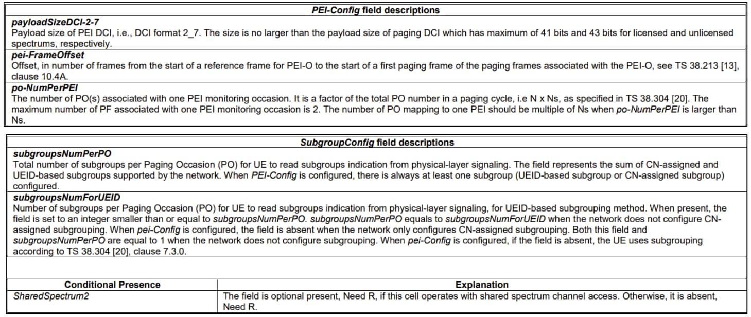
In order to reduce UE power consumption due to false paging alarms, the group of UEs monitoring the same PO can be further divided into multiple subgroups.
With subgrouping, a UE shall monitor PDCCH in its PO for paging if the subgroup to which the UE belongs is paged as indicated via associated PEI.
If a UE cannot find its subgroup ID with the PEI configurations in a cell or if the UE is unable to monitor the associated PEI occasion corresponding to its PO, it shall monitor the paging in its PO.
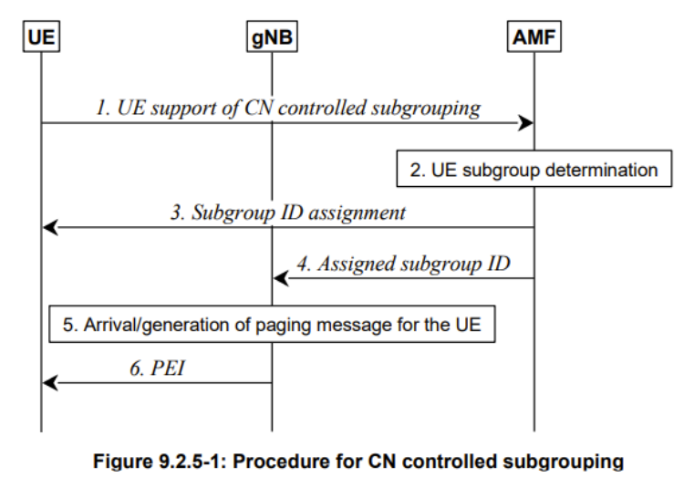
AMF is responsible for assigning subgroup ID to the UE * The UE indicates its support of CN controlled subgrouping via NAS signalling.
If the UE supports CN controlled subgrouping, the AMF determines the subgroup ID assignment for the UE.
The AMF sends subgroup ID to the UE via NAS signalling.
The AMF informs the gNB about the CN assigned subgroup ID for paging the UE in RRC_IDLE/ RRC_INACTIVE state.
When the paging message for the UE is received from the CN or is generated by the gNB, the gNB determines the PO and the associated PEI occasion for the UE.
Before the UE is paged in the PO, the gNB transmits the associated PEI and indicates the corresponding CN controlled subgroup of the UE that is to be paged in the PEI.
The gNB and UE can determine the subgroup ID based on the UE ID and the total number of subgroups for UE ID based subgrouping in the cell. The total number of subgroups for UE ID based subgrouping is decided by the gNB for each cell and can be different in different cells. The gNB determines the total number of subgroups for UE ID based subgrouping in a cell. The gNB broadcasts the total number of subgroups for UE ID based subgrouping in a cell. UE determines its subgroup in a cell. When paging message for the PEI capable UE is received from the CN at the gNB or is generated by the gNB, the gNB determines the PO and the associated PEI occasion for the UE. Before the UE is paged in the PO, the gNB transmits the associated PEI and indicates the corresponding subgroup derived based on UE ID of the UE that is paged in the PEI.
TS 138 331 - V17.7.0 - 5G; NR; Radio Resource Control (RRC); Protocol specification (3GPP TS 38.331 version 17.7.0 Release 17)
TS 138 473 - V17.7.0 - 5G; NG-RAN; F1 Application Protocol (F1AP) (3GPP TS 38.473 version 17.7.0 Release 17)
TS 138 300 - V17.7.0 - 5G; NR; NR and NG-RAN Overall description; Stage-2 (3GPP TS 38.300 version 17.7.0 Release 17)
WAKE UP SIGNAL (WUS)
WUS (Wake Up Signal) is a type of power saving mechanism introduced in NR release 16. WUS tries to save power by letting UE to continue to sleep (i.e, No Wake up) even for DRX OnDuration period when there is no data for the UE and gNB notifies the UE of ‘No Wake Up’. When there is any data for the UE, gNB would notify the UE of ‘Wake Up’ so that UE wakes up and receive data during OnDuration time.
Most UEs can be configured for discontinuous reception (DRX) - remaining in an idle state for a certain period, waking up periodically to check for traffic on the PDSCH. Currently, when configured for a long DRX period, the UE will wake up at the scheduled time and stay awake for the entire duration of the configurated “on” period. Release 16 introduces a new downlink control information (DCI) format that can be read by the UE before the long DRX wakeup time. This short DCI can inform the UE if there is no relevant downlink traffic on the PDSCH, enabling it to return immediately to an idle state through the next “on” duration.
The wakeup signal may have only minimal impact on the power a phone’s consumption. It will, however, have a much more significant effect on the power consumption of non-smartphone UEs such as IoT devices and sensors, many of which by design remain in an idle state for long periods - weeks, months, or even years - waking up only to transmit or receive information only when an event occurs
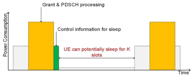
Enhanced cross-slot scheduling:
Release 16 adds the concept of enhanced cross-slot scheduling, which enables a UE to go into a microsleep state, rather than performing some non-essential decoding tasks, if applicable. A new bit field in some DCI formats informs the UE in advance if the time between the uplink or downlink control information slot and data slots is sufficient to enable microsleep, an intermediate low-power state that reduces current draw without impacting performance
Adaptive MIMO layer reduction:
Adaptive MIMO layer reduction in Release 16 creates the ability to adaptively reduce the number of downlink MIMO layers in a transmission, saving the UE a significant amount of power by allowing the UE to reduce the number of antennas in use. For example, the initial bandwidth part - set of contiguous common physical resource blocks (PRBs) - can be configured for a single MIMO layer, while other bandwidth parts could use a higher number of MIMO layers. The adaption of the maximum number of downlink MIMO layers is done on a per-bandwidth part basis.