Hi Experts.
What is the difference between analog, digital and hybrid beamforming?
And what is the frequency band preferability of each of these beamforming (sub1, sub6 and mmW)?
Hi Experts.
What is the difference between analog, digital and hybrid beamforming?
And what is the frequency band preferability of each of these beamforming (sub1, sub6 and mmW)?
Analog signals may be limited to a range of maximum and minimum values, there are an infinite number of possible values within that range.
The waves of a time-versus-voltage graph of an analog signal are smooth and continuous. Conversely, digital signals have a finite set of possible values and are one of two values such as either 0V or 5V, for example, and timing graphs of these signals look like square waves.
To identify whether a signal is analog or digital, compare how the signal appears; a time-versus-voltage graph of an analog signal should be smooth and continuous while digital waves are stepping, square, and discrete.
Most basic electronic components like resistors, capacitors, inductors, diodes, transistors, and amplifiers are analog.
Digital circuits use digital, discrete signals using a combination of transistors, logic gates, and microcontrollers.
An analog to digital converter (ADC) allows a microcontroller to connect to an analog sensor to read in an analog voltage.
A digital to analog converter (DAC) allows a microcontroller to produce analog voltages.
A digital down converter (DDC) preserves information in the original signal and is often used to convert analog radio frequency or intermediate frequency down to a complex baseband signal.
About Hybrid: it can be used to partition beamforming between the digital and RF domains. System designers can implement hybrid beamforming to balance flexibility and cost tradeoffs while still fielding a system that meets the required performance parameters.
In other words, it’s developed by combining multiple array elements into subarray modules. A T/R module can be dedicated to multiple elements in the array; thus, the system will require fewer T/R modules. The number of elements in each subarray can be selected to ensure that system-level performance is met across the range of steering angles.
Using the transmit path as an example, each element within a subarray can have a phase shift applied directly in the RF domain, while digital beamforming techniques based on complex weighting vectors can be applied on the signals that feed each subarray. Digital beamforming allows for control of the signal for both amplitude and phase on signals aggregated at the subarray level. For cost and complexity reasons, the RF control is typically limited to applying phase shifts to each of the elements.
Here you can find some information for “Massive MIMO in Sub-6 GHz and mmWave:
Physical, Practical, and Use-Case Differences”:
Mostly, ABF is used with mmWave.
DBF is used with cmWave and dmWave.
For 5G we are using Digital Beamforming for FR1 and Analog Beamforming for FR2.
Need to understand what use of hybrid beamforming.
Is it used in 5g or not?
Most of AAU use hybrid beamforming in FR1 too.
Ok thanks. I find only digital beamforming. Maybe some vendors used.
Any vendor using hybrid beamforming solution for NR anyone having idea?
I think mostly vendors are prefer to use Digital Beamforming below 6 Ghz but for above above 6 Ghz preferably use Hybrid Beamforming as they have less numbers of RF chains which is cost effective solution.
Thanks !!
For FR1 generally it’s digital beamforming.
For FR2 it’s analog beamforming.
Please tell any vendor having solution for hybrid beamforming as of now.
1 more point < 3 GHz still classical antenna used with FDD with 15Khz scs.
Now NR is mature technology please tell what is most commonly used frame structure with TDD among vendors for high throughput gain is it semi-static or TD-LTE.
7:2 one slot both dl/ul
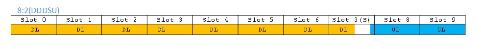
DDDSU
I think 8:2 most common and carry high throughput in DL with 5ms periodicity means each slot length is 0.5ms with SSC 10:2:2.
SSC: Special Sub-frame Configuration.
In 7:3, Periodicity DL to UL 2.5ms carry less DL slot.
Yes. This we called 7:2 because 1 slot contain both DL and UL symbols.
What do you mean by 10:2:2?
I understand there is 1 special slot but didn’t get the idea of the ratio 10:2:2 for SCS.
Could you please elaborate?
Also, what do you mean by saying DL to UL is 2.5ms?
Also over 7:3 I have low Downlink Throughput because having less DL slots Yes?
It means the amount of symbols for DL, Switching, UL.
So 10:2:2 mean? 10 is? 2 is? 2 is?
A pleasure to clarify please. 
Sir, cannot be more clear. Symbols for DL, switching and UL. 
These are the distribution of the 14 symbols.
Similar to TDD LTE symbols 10-2-2 and while ducting we change to 3-9-2?
10:2:2 is one of the Special Subframe configuration in 5G same like LTE TDD.
In every 2.5ms is shift from DL slot to UL slot. for 7:3 comparatively less number of DL slot with 8:2 but periodicity is different.