Introduction
To know the equipments used in their work is a basic need for any professional. And understand its features and functions (applications) often represents the difference when getting a new job, or finding solutions to problems.
In the Telecommunications & IT area we have a wide range of equipment (or components), which vary according to the specific area of expertise. For each of these equipment you can find a huge documentation available in the form of catalogs, courses, white papers, presentations, etc.
Many times however the basics - the most important - are not fully understood by all, even by those who use it in practice.
With the goal of explaining in a simple way the main features of RF components, we initiate today this new series here at telecomHall.
However we’ll not delve into details as calculations and definitions - more extensive or complex. Let’s just stick to the main objective: to meet the basic and essential part of each equipment. With this basis, any deepening in the studies can be done more easily, if you want.
And to start, let’s meet two of these elements: the RF Power Splitter (or ‘Splitter’) and the RF Power Combiner.
So, let’s see in a simple way the RF components: Splitter and Combiner.
RF Power Splitter
Let’s start with one of the most simple and intuitive of these components: Splitter.
Splitter, as the name implies, split (or divide).
In nature we can see an example of splitter on a river that has an obstacle, and splits into two. In this case, part of the water continues down a path, and another part by another way.

In the case of RF Splitters, instead of water, it is the RF signal that is splitted - in that case the input signal is ‘split’: the form remains unchanged, but the ‘power’ is splitted. For this reason, the RF splitters are known as RF ‘Power’ Splitters.
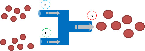
In the following figure, we see a simple illustration of a Splitter. The signal (represented by large red circles) goes in one side and out the other two ( B ) and ( C ).
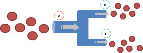
Note that the output signal is the same (has the same form), but each output has ‘half’ the power of the original signal (small red circles).
![]()
Basically, that’s what the splitter does. And the next question then would be: ‘Why or where do I use the splitter?’.
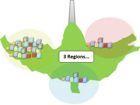
Imagine the following situation: a small rural community was contemplated by the RF planning of your company with the installation of a new BTS. The point for the installation of the Tower has already been acquired: its on a small hill in the Centre of 3 small regions, with good line of sight to all, as seen in the figure below.
Unfortunately, for reasons of ‘cost reduction’, the BTS has only 2 cells.
But there are 3 regions to be served (covered). And then, what to do?
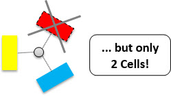
Ok, we know that in the case shown above the ideal solution would be the installation of 3 cells – but we don’t have this configuration available! Given this scenario, the alternatives would be leaving one of the small communities without coverage or … install a divider (splitter).
We can minimize the problem presented by simply using a divider (splitter) – split one cell into 2 cells, attending all 3 regions of interest, and achieving the satisfaction of a larger number of people (all potential new customers).
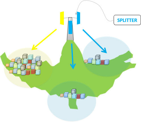
An important observation in the case above is that the cell that is ‘NOT’ divided (yellow in the figure) should cover the denser region, because that is what will have the greatest traffic. And the cell that will be divided will cover simultaneously the other 2 smaller regions (in blue in the figure).
In addition, each of the two cells in blue has half the power of the yellow sector (considering the same transmitter power for each one). This 3 dB difference must be taken into account so there’s no loss of quality, mainly in ‘indoor’ regions. Anyway, this can be fixed through adjustments, if for example it is possible to increase the power of the transmitter. Will depend of course on how is the quality in the regions met – usually in cases like this, we don’t have many losses in practice.
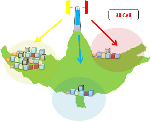
And as already mentioned, this is not the ‘final solution’, but it sure is the best action to take, considering the scenario above - cover all small regions. In the future, with the development and progress of each of these regions (and consequently greater use of telecommunications services) we will have then justifications for expansion of the third cell in BTS.
Ok, we’ve seen how an RF Power Divider works, and also a good example of its implementation.
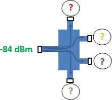
But the dividers not only divide for 2 outputs. We have for example a splitter with 4 outputs. In this case, each output will be 1/4 of the original signal strength (remember that dividers always divide ‘equally’ the input signal between all outputs).
Note: one of the most important points when it comes to RF Dividers is the insertion loss, i.e. the loss that we’ve added to the system when we inserted such elements. The bigger the loss entered in the system, the lower part of the signal will arrive at your destination, which is bad.
So when we talk about that in a 4 outputs splitter will have 1/4 of the original signal strength on each output we’re ‘disregarding’ the loss by inserting the component itself, and considering only the loss resulting from the division of signal (whose order of magnitude is much larger).
So in practice what are the losses that I have using the RF Splitter (splitter)?
Assuming NULL the loss by inserting the element (i.e. kept the characteristic impedance of the system), and taking into account only the loss by dividing the signal into more outputs, we have the following correspondence table of ‘Number of Output Ports’ x ‘Power Level Reduction’ in a Divider (splitter).
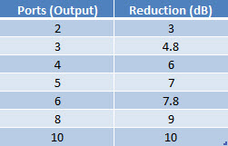
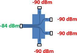
For example, if at the input of a 4 output divider we have a signal of -84 dBm, there will be a signal of -90 dBm in each one of its outputs.
Another important information regarding RF Power Dividers (splitters) is about isolation, i.e. a signal should not interfere with the other. For this, it is important to know the characteristics of construction.
Its construction can be through the use of resistors or transformers, being these last used in examples like the above. But beyond our scope today, and later we’ll explain in a simple manner its construction and operation, explaining in more detail how this isolation works.
For now, just know that all RF Splitter are passive elements, i.e. you don’t need power.
Yet we are also NOT analysing other aspects such as different frequencies or technologies. Let’s first understand the most important aspects (main) in its simplest form. In the next series of tutorials let’s gradually assimilating the countless possibilities of combination and use of such equipment.
At this point then we already know the RF Power Divider, we understand its basic operation and for what it serves, and we also saw a practical example of use.
Let’s continue and learn a ‘new’ RF component.
What do you think would happen if we reversed the use of equipment that we showed at the beginning of this tutorial?
RF Power Combiner
If we reverse the use of equipment shown at the beginning of the tutorial, inputting 2 different signals on ports (B) and (C), we have the sum, or ‘combination’ of these signs on the output (A).
You’ve probably noticed that, actually, the combiner is nothing more than a divider, but used in the reverse way, right?
And that’s exactly what it is: a RF Power Combiner simply combines (sum) different signals in a single output. In the above case, the signals are transmitted over port B and C go out through that output (A).
In the same way as the divider, the name is suggestive: the combiner combines! At first you can find very simple … and it really is, but it is extremely important for all systems where we need group (and ungroup) signals with same or similar characteristics.
The RF Power Combiner then are used in applications where it is necessary to transmit/send multiple signals over a single medium.
We will use the same example above, to see how this is done. A user (in yellow in the figure) transmits his conversation, which arrives via antenna (1) to the BTS (2). Another user (red) also broadcasts their conversation, only via antenna (3) until the same BTS. On BTS then these signals are present (summed or combined), and the BTS can then continue the processing of each one of the calls.
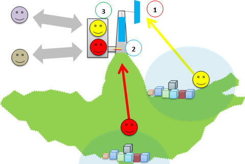
See that the different signals of each one of the users (yellow and red) were then summed (or combined) in a combiner, and both signal followed by a single cable from antennas to the BTS.
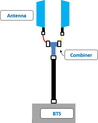
The combiner doesn’t make any kind of transformation or change in the signal. Simply combines them into a single output.
And also it is easy to understand that all the features as Loss and Isolation of RF Power Combiner are the same we’ve previously seen for the divider. As the divider, the combiner is also a passive element.
Ok, you now know what is a RF Power Combiner!
What we’ve seen so far applies to signals that have the same characteristics, no matter the frequency: the splitter and combiner ‘don’t care’ about the frequency.
But what about when we need to convey different and specific frequencies via a single broadband antenna, what do we do?
In this case, we need to ‘adjust’ the RF filters to ensure that interconnection in a single transmission medium.
But this is already subject to the next tutorial in this series.
Conclusion
We completed the first tutorial in the series of RF components, understanding in a simple way what are and what are they for: RF Power Combiners and Splitters. Now we are prepared to meet and understand other elements (the next tutorials).
It is very important that these basic concepts (in a simple way) are well understood, because it is very common that questions arise in the definitions between these elements and other elements that we’ll see in sequence.
In fact, there may be doubt even among combiner and splitter, because we have seen that a combiner can be used as splitter and vice versa. That is, often the difference is only in use.