Wireless communication systems require the proper integration of several components. For example, antennas are connected to the transmitter/receiver, as well as switching and signal processing equipment by means of a coaxial cable. It is important that these components are “matched” from an RF standpoint, otherwise, reflections occur. Reflections affect the overall performance of our system. If the level of reflections becomes excessive, the quality and performance of our system are greatly degraded.
Thus, a wireless communications system is similar to connecting several garden hoses together with a sprinkler. If the hoses and sprinkler are properly matched, the sprinkler distributes water to the outside environment, covering the desired area. If not, the sprinkler either dribbles water out to the outside environment (loss of signal power) or doesn’t work at all. Although this example is rather simplistic in form, we get the idea!
RF energy travels through transmissions lines (coax cables) just like sound travels through an empty room. It is susceptible to reflections and bounces. When sound waves hit the hard walls of an empty room, you can hear the echoes. When we send RF down a coax, we want it to go into the antenna (then radiate out into the world). We do not want it to bounce back towards us like sound in an empty room.
What is Return Loss ?
Return loss (RL) is a very important noise measurement.
RL is a summation of all the reflected signal energy coming backward toward the end where it originated. It is like an echo and must not be confused with crosstalk. The echo is real data, but since it interferes with the desired signal, it must be treated as noise.
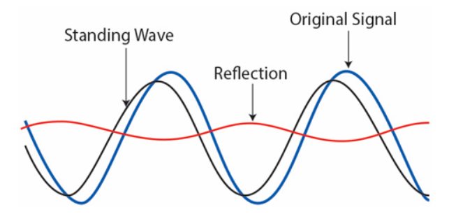
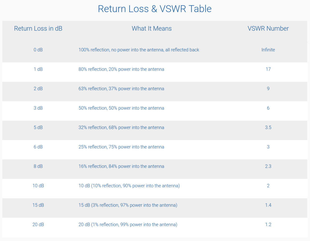
Return loss is the measure of how small the “return” or reflection/echo is. We want a small return, so a large loss on the return “echo” is good. Smaller return loss is bad, and means less energy is going into our antenna. RF engineers often measure return loss on a “dB” logarithmic scale, which can make it seem more complicated than it really is. However, just remember better return loss is indicated by bigger return loss numbers, and that is better for your antenna. Here are some examples of the logarithmic scale, or loss in decibels and comparison with VSWR:
What is the difference between return loss and VSWR ?
For many engineers, there is no functional difference between return loss and VSWR (Voltage Standing Wave Ratio); after all, they are measurements of the same parameter. They both measure the amount of RF signal transmitted by a connector that is reflected back.
So what separates the two?
Return Loss is the portion of a signal that is lost due to a reflection of power at a line discontinuity. Return Loss is similar to VSWR and is generally preferred in the cable industry to a VSWR specification. Since it is a logarithmic measurement, it is very useful when displaying very small reflections.
VSWR is the ratio of voltage applied to voltage reflected. VSWR is similar to Return Loss and is generally preferred in the connector industry to a Return Loss specification. Since it is a linear measurement, it can be useful when displaying larger reflections due to the fact that small differences are not compressed as they are in a logarithmic measurement.
What Causes Return Loss ?
There are two major causes of RL in a network: discontinuities and impedance mismatches. Discontinuities occur at connections where cable is terminated to plugs or jacks and within the plug/jack connection itself. A discontinuity can also occur if a cable is bent too much, kinked or otherwise damaged. When a transmitted signal pulse hits one of these structural discontinuities, echo or RL occurs.
Impedance mismatches can be macro or micro in scale, and both are important. Macro mismatches are usually component-to-component related.
Micro impedance variations along a cable’s length are subtler but also important contributors to RL. Manufacturing tolerances during the construction of a coax cable causes these variations. The precise impedance is determined by the insulation material used, the diameter of the copper, the diameter of the insulation and the centering of the copper within the insulation. If any or all of these factors vary during the manufacture of a coax cable, the impedance will vary along its length. These micro variations in impedance along a cable are small, but they affect high frequency signals, adding a cumulative signal echo.
A perfect transmission line would have no imperfections, connections or impedance variations along its length, and therefore would have no return loss confusing the receiver. However, this is the real world and our networks are built using coax cables with plugs and jacks as connections. Too much RL noise resulting in increased bit error rate, lower signal to noise ratio, less network operating margin and more downtime.
The first and most important component the signal sees is a flexible patch cord. This is why patch cord quality is becoming critically important for networks migrating to higher speeds.
Measuring VSWR/ RL Values of Cable and Antenna System at Site.
Now let us focus on the problems of VSWR/RL, associated with cables and antennas at the site. Normally it has been observed that of all the problems of VSWR reported at the site:
- 60% are connector related
- 20% are cable related
- 5% are antenna related
Probable causes for most of the cable and antenna problems are many like connector transitions, jumpers, kinks in the cable or moisture intrusion. The best way to measure the VSWR/Return Loss at the site is to conduct a system RL/VSWR sweep, with the help of instruments like Agilent or Anritsu’s Site Master or BTS Master. Since each site is configured differently, it is natural to get separate sweep values at different sites.
Typical values of good RL values for a site vary between 14–20 dB, depending upon the configuration of the system.
The best method for fault finding of a cable and antenna system, in terms of VSWR/RL is to use DTF (Distance to Fault measurements) to calculate and compare different RL/ VSWR values.
The DTF measurement displays return loss (or VSWR) values versus distance. If the frequency measurements fail or indicate a problem in the system, then the DTF measurement can be used to identify and pinpoint the exact location of the problem. The DTF measurement shows the return loss value of all the individual components including connector pairs and cable components.
To measure the distance of a cable, DTF measurements can be made with an open or a short connected at the end of the cable. The peak indicating the end of the cable should be between 0 dB and 5 dB.
An open or short should not be used when DTF is used for troubleshooting because the open/short will reflect everything and the true value of a connector might be misinterpreted and a good connector could look like a failing connector.
A 50Ω load is the best termination for troubleshooting DTF problems because it will be 50Ω over the entire frequency range. The antenna can also be used as a terminating device but the impedance of the antenna will change over different frequencies because most antennas are only designed to have 15 dB or better return loss in the pass band of the antenna.
DTF measurement is a frequency domain measurement and the data is transformed to the time domain using a complex mathematical function called Discrete Fourier Transformation.
Summary and Conclusions.
RL performance is usually an end effect and therefore very dependent upon patch cord and connector quality. This distortion is in many ways the worst effect of all, because signal equalizers cannot be made “smart” enough to compensate for this loss.
Cramming more and faster signal data into the same period of time means using higher frequency, lower energy signals that will be more susceptible to noise.
High quality patch cords, built with the best plugs, actually reduce channel return loss and increase channel performance margin. This, in turn, reduces bit errors, signal distortion, and retransmissions. Channel throughput is increased, resulting in less downtime, less troubleshooting and happier network users.