Introduction
Have you ever heard of “Rake Receiver”? Surely you’ve heard of Receiver (Receiver in English), and you probably have heard of Rake (Rake in English).
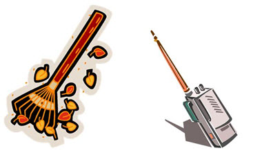
With the pictures bellow, can you imagine what a Rake Receiver can be?
Ok, if the analogy does not help much, let’s go.
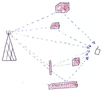
In a wireless communication system, the signal can reach the receiver via multiple distinct pathways.
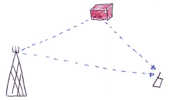
In each path, the signal can be blocked, reflected, diffracted and refracted. The signal of this many routes reach receivers faded. The Rake receiver is used to correct this effect, selecting the correct / stronger signals, bringing great help in CDMA and WCDMA systems.
Okay, but what is the Rake Receiver, and how it does it?
Definition
The Rake Receiver is nothing more than a radio, whose goal is to try to minimize the effects of the signal fading due to multipath suffers when he travels. In fact, we can understand a set of Rake Receiver sub-radios, each lagged slightly, to allow the individual components of the multipath can be tuned properly.
Each of these components is decoded completely independently, but are combined in the final. It is as if we took the original signal, and adicionássemos other copies of the original signal reaching the receiver with different amplitudes and arrival times. If the receiver knows the amplitude and arrival time of each of these components, it is possible to estimate the channel, allowing the addition of components.
Each of these sub-radios Rake Receiver is called Finger. Each finger is responsible for collecting the energy of bit or symbol, hence the analogy with the groomer that we use in the garden, where each branch of the rake collecting twigs and leaves!
To ease some of the understanding, imagine two signal components arriving at the mobile unit as seen in the previous figure, with a lag ∆t among them.
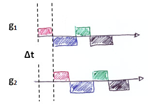
Notice how each Finger works:
-
The first with component g1 and time reference t ;
-
The second with component g2, but with the time reference t - ∆t .
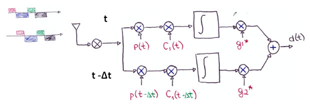
The Fingers are so receptors that works independently with the function of demodulating the signal, ie, receive and remove the RF components from the information.
The big idea behind the methodology of combining multiple copies of the transmitted signal to obtain a better signal is that if we have multiple copies, probably at least one must be in good condition, and we have more chance of a better decoding!
Key Benefits
The main advantage of Rake Receiver is that it improves the SNR (or Eb / No). Naturally, this improvement is observed in larger environments with many multipaths than in environments without obstruction.
In simplified form: we have a better signal than we would have without using Rake Receiver! This is already a sufficient argument, isn’t it?
Disadvantages and Limitations
The main disadvantage of Rake Receiver is not necessarily technical, and is not as problematic. This disadvantage is primarily because the cost of the receivers. When we insert one more radio receiver, we need more space and also increase complexity. Consequently, we increase costs.
The greater the number of multipath components supported by the receiver, the more complex is the algorithm. As we always do here, we will not be deducting formulas involved, but the complexity increases almost exponentially.
And in the real world, the amount of multipath components that arrive at the receiver is quite large, there is not a ‘limit’. Everything will depend on the environment.
The threshold number of fingers in a mobile unit is determined by each technology standard, which for example in CDMA is 6, corresponding to the maximum number of channels to direct traffic that can be processed by the mobile unit at once (Active Set).
However, in cellular environments, most of the CDMA mobile units need only actually 3 of demodulators (WCDMA uses 4). More than that would be a waste of resources, and an additional cost to manufacture the phone.
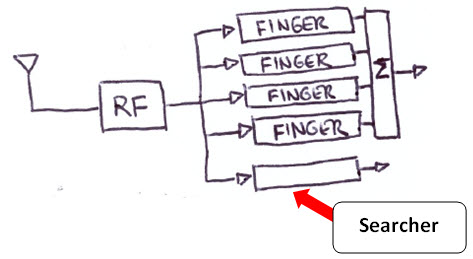
Searcher
An important detail in the CDMA and WCDMA systems is the use of one finger of the Rake Receiver as a ‘Searcher’. It is so called because of its function of seeking pilot signals being transmitted by any station (BS) in the system. These pilot signals can be understood as beacons used to alert the mobile, the presence of a BS.
Thus, in the UMTS UE(User Equipment), we have a simplified form of the configuration of the Rake Receiver as below.
Fingers on BS and UE
To conclude, the number of Rake Fingers used in the BS and the UE is generally different. That’s because we saw that to have more fingers, the physical size of the receiver increases, as their power requirements. This can be a problem for the UE but not a problem for the BS, since it is able to offer more space and power for new fingers. It is only the criterion of cost to be taken into account in the BS.
Anyway, the only critical issue is with UE. But the current three/four fingers ensure excellent gain proven in practice (CDMA/WCDMA).
Conclusion
We saw today that the Rake receiver is used in CDMA and WCDMA as an efficient way of multipath signal reception, where several recptores are able to reconstruct the signal with different time-codes, amplitude and phase.
Comments are important and welcome!