Introduction
Perhaps you’ve heard that some mobile devices consume less or more battery than others.
Or you may have heard the following: “When I put my mobile in LTE mode, it drains more battery.”
Unfortunately, this is true, especially in the case of LTE. This is one reason why the first LTE devices became known as ‘bad’ - battery drainer.
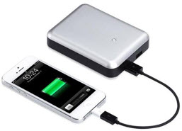
The ‘solution’ adopted by some manufacturers has been to increase the size of the batteries. And nowadays, it is not uncommon to find people carrying an extra battery. (The battery was increased to compensate for the ‘waste’ of energy, as we shall see soon).
Analyzing some characteristics of the mobile access technology, we see that more and more increase the complexity (red in the table below).
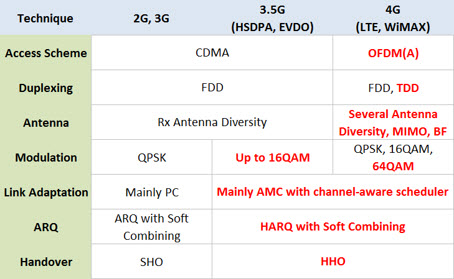
Though this complexity is required to support high rates increasingly demanded, they end up bringing about some disadvantages.
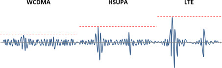
The main one, and technical explanation for the higher battery use in LTE is due to the specific characteristic of the RF OFDM (A) signal waveform, where the waves have “peaks” and “valleys” more extreme than their predecessors (3G for example), so that they can be achieved high data throughput with limited spectrum resources.
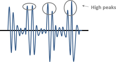
When we are comparing typical WCDMA, HSUPA and LTE signals, we see clearly that the peaks in LTE are more prominent.
Important note: Of course there are other factors that can cause a mobile LTE drain more battery than a 3G mobile, but certainly this ratio is the most striking: the signal strength ‘peak/average’ ratio.
So let’s know what it means that ratio. Consider now a typical output signal of an OFDMA transmitter (LTE). The red line indicates the Peak, and green the Average RMS (signal strength).
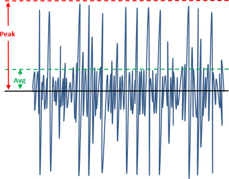
The ratio of peak power to average power is referred to as PAPR (Peak-to-Average Power Ratio).
But how can I better understand this ratio?
By means of example. Suppose that in the signal above the average is 200 mW. And the peak signal reaches 2 W. Then, so that we can transmit all the signal (which has an average of 200 mW), the amplifier must be able to handle a ten times higher signal (10 dB) that, ie , a power of 2W.
Congratulations: you just saw in practice what it means PAPR equal to 10 db!
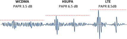
Practical values (typical) of this ratio varies depending on the technology (or more precisely to the shape of characteristic waveform. For example, for WCDMA is around 3.5 dB, for the HSUPA around 6.5 dB and LTE about 8.5 dB.
Let’s move on, and consider an RF LTE signal as shown below.
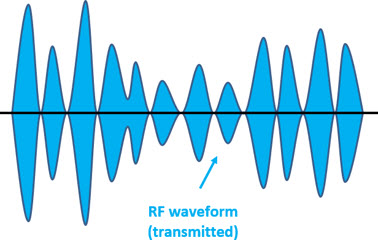
Important Note: For simplification purposes, we ‘envelope’ the RF signal, ie the displayed waveform is the ‘envelope’ of the actual RF waveform, as shown below.
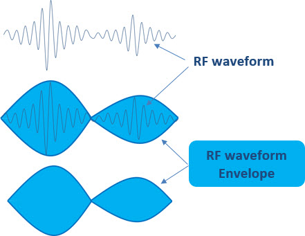
Understood the envelope concept, and as we have demonstrated the waveforms in this tutorial, we will continue.
Constant Output
To ‘support’ all this signal a battery should have a constant level, as shown in the figure below, in yellow. In orange we have the part that is lost - dissipated as heat.
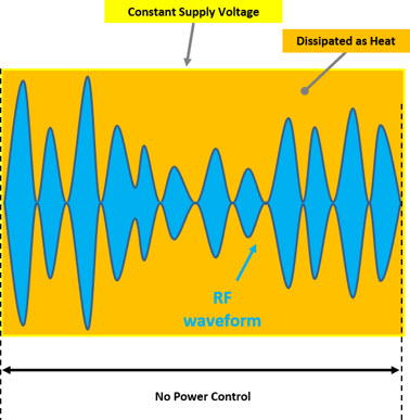
In other words, the simplest possible form for a power system would be a direct connection to the battery, with a continuous signal level (independent of the RF signal). But in this case, it is easy to see that efficiency would be extremely bad, since it is directly related to the PAPR waveform.
In cases such as shown (Continuous Output) comparing the WCDMA versus LTE consumption, the LTE consumes almost twice (two times) than the WCDMA.
Amplifier Efficiency
We said above that the power amplifier has a ‘bad efficiency’. But what does it mean?
Taking advantage of this our first example, let us understand what is the ‘efficiency’ of RF amplifiers, since from it depends on the design of many other elements, such as which source of energy that will be used, if we have heat sinks or not , etc. In other words, the RF design of all modern mobile systems depend on the ‘efficiency’ of RF amplifiers.
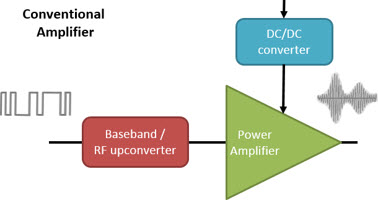
In an RF amplifier, power is supplied to the circuit, and an output signal is generated (always less than the DC input power).
The ratio of output power on the input power (DC) is what we call Efficiency.
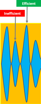
If the signal being processed has a fixed shape (modulated signal but with fixed amplitude) and the amplifier doesn’t need to be adjusted, we have a high efficiency.
However, the waveform of modern cellular systems and amplifier operation mode set the Efficiency.
And that is why alternative techniques emerge, as discussed below.
Amplifier APT (Average Power Track)
Continuing from the above example, we saw that it is the worst possible case: a system which we do not have any power control. In fact the power control exists (at intervals of periodicals times the energy is varied).
And the most common solution used is the APT (Average Power Track) amplifier circuit .
In APT DC: DC solution, each slot is tracked based on the transmission power control levels.
In cases of low power, this solution actually improves the efficiency, but does not help much in cases of high power. Furthermore, the efficiency also depends on the waveform.
In APT mode according to a certain periodic time, the drain voltage of the battery is adjusted by the device - however this value remains until the next control slot! But even if the voltage is adjusted, just waste much of the energy - ‘leveling up’. The PA must be adjusted so that the power ‘settle’ peaks and valleys.
In the figure below, we see again in yellow the battery powerand in orange the amount of energy wasted. In other words, we consume more energy than necessary!
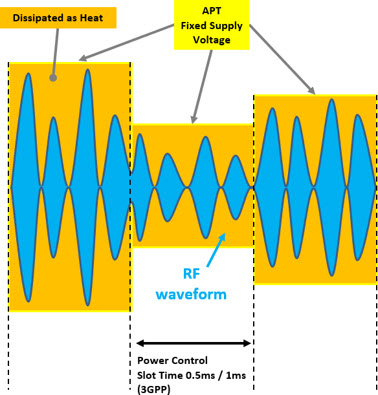
Ideally, we should not have orange area, ie, the device should pull the battery only the energy it needs to transmit.
It sounds simple, but it was actually a very difficult thing to accomplish, especially in LTE smartphones, as we have seen they consume much more energy in your power amplifiers than the 3G or 2G devices.
Fortunately, this story has changed. The company Nujira has developed (and is already commercial for a long time, even with numerous devices available on the market) a new technique that eliminates this huge waste that we have in these radios (especially LTE).
ET (Envelope Tracking) Amplifier
The new technique is called Envelope Tracking. Disregarding the intuitive concept of envelope we use when we send a letter to someone (although the concept is similar) in the Engineering and Physical envelope concept refers to a function. For any oscillating signal, the envelope is a smooth curve that involves, or outlines its limits. The signal is contained within the envelope.
You may not have noticed, but we have previously talked about it (we gave a hint). The signals that we represent in this tutorial have an envelope shape!

So it’s easy to describe: ET (Envelope Tracking) is the technique that ‘match’ the energy that is powering the device with the power it transmits.
This scheme is much more dynamic than the APT, and allows tracking of the signal amplitude.
Using ET, the voltage of the power source applied to the amplifier is continuously adjusted to ensure that the device is always operating at its peak efficiency so that the desired power output.
Unlike the APT it does not depend on the waveform. And with the use of ET the LTE consumption is very close to the WCDMA (about 1.2 times).
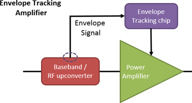
The baseband signal powers the chip (ET) and varies the DC power source so as to maintain the PA at compression point (or at least close to it), resulting in far greater efficiency.
Another difference compared to the APT is that the ET replaces the fixed DC source with a variable DC power supply (rapidly changing) that dynamically tracks the amplitude (or envelope) of the RF signal. The signals of the mobile baseband Chipset are sent to ET power supply chip.
Returning to the same previous figure, but now with the ET instead of APT, we see that the orange area (waste) is minimal!
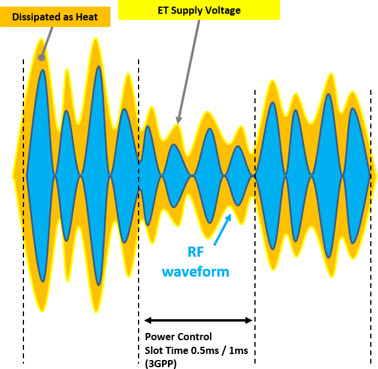
The goal of the ET is reached: get efficient power conversion. Namely, that every moment is provided only the necessary energy (for that time of transmission). Although this exact relationship is practically impossible to achieve the continuous adjustment to the PA allows us a very good approximation.
Comparisons
Comparing oversimplified way the 3 implementations, we can clearly see that energy is better utilized with the use of Envelope Tracking technique.
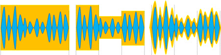
In practice, the efficiency of a conventional amplifier (APT) is around 25%, while with the ET is around 60%.
Availability
As already mentioned, the ET has been available for some years. Samsung for example debuted with Qualcomm QFE1100 chip in the Galaxy Note 3. LG with the Nexus 5. Apple with iPhone 6.
Currently, its use is very wide - virtually all new models of all manufacturers.

Conclusion
Over time, several techniques were used in order to improve the efficiency of power amplifiers in communications systems, each with its advantages and disadvantages, but all with the same goal - to improve the efficiency and linearity of power amplifiers and consequently reduce energy consumption (which costs money) of BS (Base Stations) and to save the battery of mobile (prolonging the duration of use and decreasing heating).
We have seen here today some of these techniques such as ATP and ET (Envelope Tracking), the latter being most appropriate - and used - in modern cellular systems, such as LTE, with a high PAPR (Peak-to-Average Power Ratio).
We have also seen that Envelope Tracking technique is very effective, and includes a new component - the amplitude, which is now tracked and used as input: the ‘envelope’ of signal amplitude is tracked and used by the amplifier!
We hope you have enjoyed.