Introduction
Regardless of the pace of LTE networks deployment around the world (faster in some areas, slower in others), the number of users with 4G devices is intensively growing.
Thanks to factors such as lower costs - due to the gain of production scale, and also by encouraging migration to 4G plans - offered by operators who already have an available network, more and more people have access to new services and benefits that this technology offers.
However, as much as the current data services are improved, and that progress in the area lead to the adoption of new services, a basic necessity should still continue to exist at least for a while: voice calls!

While making a voice call may seem simple, largely depends on the scenario where the user is, and alternatives available for its completion. So it is necessary to understand well what are the possibilities and the most important concepts of these key scenarios.
In the first generation of cellular networks, the communication through voice calls was the main goal, and was based on a circuit switched topology or ‘channels’ (CS Circuited Switched).
Over time, the need for other services (data!) has emerged. Voice calls have come into existence with these new services. As demand increasead, these new services were supported by a new domain, the IP-based packet-switched (PS Packet Switched). The following figure shows how these two domains work.
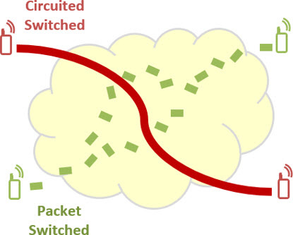
And in LTE (4G) system we had another great change: the CS domain has been extinguished! LTE networks are based exclusively on the PS domain, and voice services should be carried out in other ways (as we shall see).
But as we mentioned, regardless of network topologies, voice services are still needed. (Of course, they slightly decreased compared to a few years ago, but are still significant, ie their demand continues).
With the continue growth of LTE networks, let’s try to understand a little more the concepts, alternatives and solutions for any user to make a voice call on an LTE network?
How, when and where?
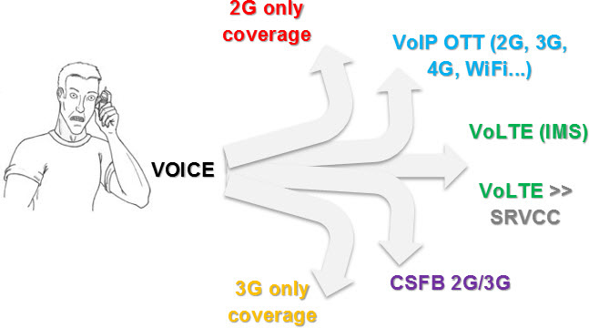
First of all, we need to understand how, when and where voice calls can occur.
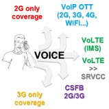
In the 2G legacy networks, voice calls are made practically only on circuits - for each call (CS domain).
In 3G legacy networks, voice services can use the CS domain, but can also be made through OTT (Over The Top) solutions, applications that encapsulate the voice and transport via an IP domain (PS), but who lack the QoS requirements needed to ensure good communication - with the Non GBR type services (no bit rate guarantee). Example: Skype. Note: It is very unusual, but it is also possible to make OTT voice calls on 2G networks. In fact, there may be OTT solutions in any technology - it can be used in legacy networks, and also in others such as WiFi - which are already commonly used for VoIP.
And in LTE networks, voice calls can be fully IP-based, can use OTT solutions via 4G, or be transferred to the legacy 2G/3G.
As we begin to see, there are many alternatives. As usual, we will easily see each one.
Note: In this tutorial, we will always refer to voice calls (originating and/or terminating); However, SMS services are also included.
Alternative to voice calls in a generic 2G-3G-4G Network Topology
And the best way to understand the alternatives or possibilities of making voice calls in LTE network (4G), it is to start from a 2G-3G-4G network topology very simplified - considering only the main elements involved.
As we can see in the following figure, the LTE (EPC) has no direct ‘link’ to the CS network - as we have seen, it is designed to take care of purely IP (PS) calls. It has no Media Gateway directly connected, so no CS call is supported by the MME.
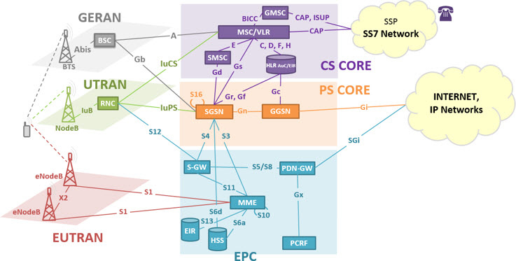
In other words, if the user or UE (User Equipment) is on a LTE network, as shown in the topology above, we can not make a voice call.
Note: As mentioned before and according to the topology above, the only way to have voice services in LTE would be through OTT services such as Skype. However, this solution is not discussed today.
If we understand this, it is also easy to realize that in order for we to have voice services in LTE, changes need to be made. There are some alternatives, and below we have the main ones:
- VoLGA (Voice over LTE via Generic Access): Use legacy 2G/3G as a generic access, ‘packaging’ voice services, and delivering via LTE.
- CSFB (CS Fall Back): whenever the UE have the need to place a call, make it revert (fallback) for legacy networks.
- VoLTE (Voice over LTE): make voice over LTE itself. In this case, the voice is pure IP - VoIP LTE.
- SRVCC (Single Radio Voice Call Continuity): ensure that purely LTE (VoLTE) calls are transferred (via handover) to the legacy networks in a transparent manner.
Note: notice that the SRVCC is an option when the voice call has been established in LTE. Ie it is a conditional alternative - considering that VoLTE option has been used.
Even without knowing very well the options presented, it is easy to imagine that the ‘best’ solution would carry voice over their own LTE network. But like everything in life, it also have the other side, the pros and cons.
To deliver voice services in LTE network is necessary to have an infrastructure that support it. In other words, there needs to exist an IMS (IP Multimedia Subsystem or IP Multimedia Core Network Subsystem). If an IMS is available, then the voice over LTE may be provided as long as a minimum set of IMS functionality and entities also are present.
Note: IMS is much more complete, and have more other purposes than the voice. The voice is just another ‘application’ of IMS, as we’ll see soon.
This minimum set of features and entities of the IMS (called VoLTE or One Voice) was standardized to enable LTE operators to provide voice services without having to make very radical changes in the network (without having to invest in a complete IMS, with all entities and functionality).
In any case, it requires investment.
And therefore the first two alternatives become attractive: based on legacy network CS infrastructure. But if on the one hand such alternatives require less investment in LTE network, these alternatives depend on the existing 2G/3G networks.
Let’s talk a little more about each of these possibilities, but always trying to maintain the overview, in the simplest possible way to understand. Remember that our goal is to learn the concept, in order to enable a deepening on the subject, if desired, more easily.
VoLGA
The first implementation alternative that emerged was the VoLGA (Voice over LTE via Generic Access), or: try to use what are already available, with minimal changes required.
To use the infrastructure of legacy 2G/3G networks, VoLGA introduces a new network entity, the VNC (VoLGA Network Controller), which basically functions as a 2G BSC, communicating with a GSM MSC (Mobile Switching Center) and as one 3G RNC communicating with a UMTS MSC (Mobile Switching Center).
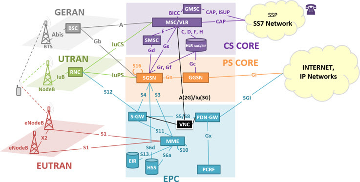
When we have a new call (be it originated or terminated), it is managed by the MSC of legacy network. VNC is who mediates the voice signal and its related messages between the MSC and the LTE network.
Although it is possible to carry out the delivery of voice and SMS services to users LTE, the Volga was unsuccessful. This is because, as we have seen, exclusive investment are needed for this purpose. At the same time however, global efforts to VoLTE increased (eg investments in IMS), and thus this alternative eventually falled into disuse.
CSFB
But if in one hand operators follow seeking a complete LTE infrastructure (with full IMS) to meet multimedia services and also purely LTE voice, this is not a topology that is available in the short and even medium term.
While that reality doesn’t come, we must use the legacy network when there is the need of voice and SMS delivery to LTE users.
And the most common alternative to this is the CSFB (CS Fall Back), an interim solution until we have full support for voice over LTE.
At CSFB scheme, whenever there is a demand for a new voice call, the LTE user is ‘backed’ for a CS legacy network, assuming that this provides an overlapping coverage. In other words, with CSFB, a voice call is never active in LTE, but in legacy networks.
At the end of the call in the legacy network, the UE can re-register the LTE network.
It goes something like this: the UE is registered (also) in the legacy network. When it got a call, the legacy network tells to LTE network: ‘I have a call to the UE, can you ask it to come here and make the call?’
To CSFB be possible, users must be using dual mode devices, ie able to operate both in LTE network and in the legacy network.
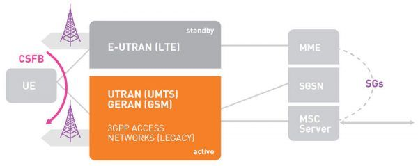
To support CSFB, a new interface is introduced: the SGs, connecting the MME to the legacy MSC.

As the CSFB is currently the most widely used option by several operators, let’s see some basic scenarios of it (CSFB).
CSFB - Registration and Location
When the CSFB UE is turned on, it registers itself in the two networks: LTE and legacy network (CS).
And to allow quick transfer to the legacy network (either 2G or 3G) when necessary, the LTE network needs to know the location of the UE.
For this, the MME, which tracks the location of the UE in the LTE network, continuously provides location information to the legacy MSC, using the new SGs interface.
The set of SGs messages then supports management of mobility, paging and SMS.
CSFB - Originated Call
We will continue, and assume that the UE is initially covered by the LTE network, and that there is an active IP connection.
When the UE decides to originate a voice call, it sends an SRM (Service Request Message) to the MME (more specifically the ESR - Extended Service Request).
The MME checks whether the UE is CSFB capable, and notifies the eNodeB to transfer the UE to the legacy network.
Before performing the UE transfer, the eNodeB can ask it to make RF measures on neighboring 2G/3G network. The eNodeB then decides the best network for the UE and performs the transfer.
Once the UE camp in 2G/3G network, it starts the call procedure as usual - the UE starts the call control procedures in legacy network.
CSFB – Call + Data Connection in LTE
And what happens if I have an active data connection in the IP LTE network, and decide to make a voice call?
There are two options:
- The data are also transferred to the legacy network, or
- The data are temporarily suspended, until I return to the LTE network.
Although the first option seems the best, we must take into account that the transmission of IP data is also transferred: it can operate at much lower speeds (legacy systems). In addition, it may be that the legacy networks deny the IP session due to lack of resources or for not being able to process it.
The S3 interface is used to carry out the PS session handover for 3G (in this case, the DTM - Dual Transfer Mode must exist, but this details escapes form our theme today).
There are no 4G data handover supported to 2G - in this case, the data is suspended.
The eRABs 4G are released when the UE performs the CSFB.
An important information is that the S3 is a ‘new’ interface between MME and SGSN on GTPCv2. And to support it, the SGSN needs to be updated (most carriers do not want to do this without a strong justification).
And Gn interface is already on GTPCv1, which is the native GTP version for 3G networks. So in this case only the MME needs to be updated, and as it is a relatively new node, it is probably easier to do. Not to mention that the new SGSN may have native support for S3.
CSFB - Terminated Call
Finally, we have the case of a terminated call for LTE user.
The call request arrives first to the MSC where the UE was previously registered.
When the MSC the receives call request, it sends paging messages to the related MME via SGs interface.
This message is forwarded to the UE, which is still connected to the LTE network.
If the user accepts the call, it sends an SRM (Service Request Message) to the MME.
The then MME notifies the eNodeB to transfer the UE for the legacy network, and the eNodeB then decide the best network for the UE to make the call.
CSFB – What happens after the end of the CS call?
We have seen that the 4G eRABs are released when the UE performs the CSFB. But what happens when the UE ends the CS call?
About what should follow next (if the UE should return or not to LTE as soon end the call CS), there is no specific rule.
Anyway, the main possibilities are:
- The upper layers forcing the ‘reselection’ to LTE so that the UE enters idle mode in legacy network.
- The operator send LTE ‘redirection’ information in RRC connection release message of legacy 3G network after the call is finished. This will result again in reselection to LTE.
- The lower layers (AS - Access Stratum in this case URRC or GRR) reselect to LTE if the reselection criterion is satisfied. In most cases, operators have their parameters set such that the reselection to LTE happen if there is a good LTE coverage area overlapping the legacy network.
VoLTE
Everything we have seen so far is based on the making of voice call in the legacy network. But as we have seen these are ‘temporary’ solutions until the ‘final’ solution - VoLTE - is available.
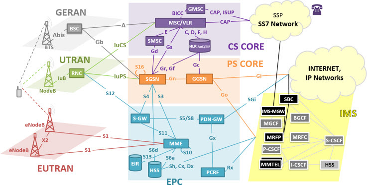
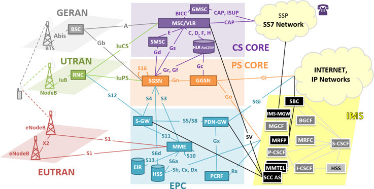
And the final LTE voice solution (Voice over IP, or more specifically VoLTE) uses the IMS backbone. An example of network topology supporting VoLTE is shown in the following figure.
To make voice calls, LTE networks need to have an IMS. When the first LTE networks appeared, they had no IMS, and without IMS, it was not possible to make any calls to any PSTN or CS.
We have spoken of the IMS before, but let’s remember.
IMS
IMS is a backbone (network) at the application level, which works on top of other wireless networks and not just the LTE (as 3G, 2G, WiFi and others).
Its concept is quite broad, and to understand it with all its entities, possibilities, interfaces, protocols, and possibilities is an extremely difficult task, even for the most experienced in the subject.
The IMS is not new: it already existed before the LTE (as well as other entities, such as the EPC PRCF, which also is not new!).
Its complete specification consists of thousands and thousands of 3GPP standards. But let’s try to understand in a simpler way than that found there.
As its name suggests (IP Multimedia Services), IMS offers several multimedia IP services, including VoIP (Voice over IP). In IMS, voice is just ‘another’ service!
IMS brings together voice features such as authentication, service authorization, call control, routing, interoperability with PSTN, billing, additional services and VAS. None of these exist in the EPC: this is the reason why the pure EPC without IMS can not process a voice call.
In other words, for VoLTE, access is made by the SAE (eUTRAN + EPC), while voice service lies in the IMS.
An analogy we can do is to consider the IMS being a car. And the LTE voice, as our shuttle service (to go from one place to another).
- We can buy a very basic car - Basic 1.0 engine, wheels, steering wheel and other minimum parts: yes, we can go from one place to another.

- Or we can buy a ‘connected’ car - ultra modern, powerful, tetra-fuel, with all the safety features, ABS, Air bag, connected to the Internet, etc: we also go from one place to another … but we can make several other things as well!
That’s more or less what happens with the IMS. It is used in conjunction with the LTE network to support voice: both full IMS implementation and also the minimum IMS suggested implementation for Voice over LTE.
But the telecommunications industry would rather not invest in a full IMS, or at least did not have sufficient reason to do it immediately. And for the adoption of the simpler IMS voice solution, appear the VoLTE initiative, which specifies a minimum set of features, and selects a simple choice when multiple options exist for certain features.
However, not all of these features are required for delivery of basic voice services by the LTE network.
So let’s illustrate with a diagram (extremely simple) the implementation of a voice in IMS (VoLTE).
- Let’s assume that we will make a VoLTE call with a CS network whatsoever, for example the PSTN (Public Switch Telephony Network).
- And consider in the IMS only two simple elements, one for the control plane (with signaling) and one for the user plane (with voice).
- And the entry being the SAE, or LTE network.
- In IMS, the control element would be a SIP server (soon we will talk about SIP - for now just understand that when we have a call request to this server, it sets up the call.); and the user element would be a Media Gateway.
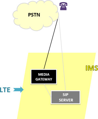
In comparison with the legacy networks, the SIP Server is equivalent to the MSC in the mobile network topology and the media gateway is equivalent to a typical Media Gateway on any network topology, which is common in virtually any voice network to handle calls.
The above concept is valid, but in practice the IMS consists of much more entities, as seen below. Note: Not all possible/existing entities and interfaces are shown in the figure.
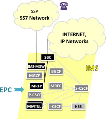
Let’s (quickly) see a little about these key elements.
Note: Do not worry or try to understand everything now about these elements. Remember that our goal here today is not that. Anyway, it’s worth a read.
The MGCF (Media Gateway Controller Function) is the control element that communicates with other PSTN networks. It is significant because it has to inter-networking function: can speak SIP, can speak ISUP, can speak other signaling protocols.
The IM-MGW (IM Media Gateway) is the element that takes care of voice functions for example making protocol translation required to support the call. More specifically between the Real Time Transport Protocol (RTP) to analog format or basic PCM in the CS network; and vice versa.
The HSS (Home Subscriber Server) is an element that also exists in the LTE EPC (although appeared first in IMS), and its functions are similar.
The MRF (Media Resource Function) provides many services related to voice, such as conferences, announcements, voice recognition and so on. It is always divided into two parts, the MRFP (Media Resource Function Processor), for media streams, and the MRFC (Media Resource Function Controller) that functions basically as an RTP ‘mixer’.
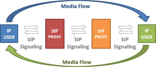
An important concept, and that’s worth stand out here is the Proxy, for example to make filters, identify where the users come from, the cases of roaming, etc. Remember that we are talking about an IP network. Instead of the users to speak directly with the SIP server, they use the proxy.
The CSCF (Call Session Control Function) has some variations.
- O P-CSCF (Proxy CSCF) among other tasks, provides QoS information related to the LTE network. Acccess an AF to voice service, and provides the control functions ‘policy’ and ‘charging’ to the PCRF.
- O I-CSCF (Proxy CSCF) is an interrogator.
- And the S-CSCF (Serving CSCF): the CSCF server acts as a central node.
The BGCF (Border Gateway Control Function) functions as a routing table (or table B) and acts to help the S-CSCF. It has basically routing decisions.
As we speak, the IMS voice is a ‘service’ - the IMS is a services ‘facilitator’. The IMS services are provided through AS (Application Servers).
One such application is the voice. And there are also video services, conference, etc.
In fact, sometimes the AS are not considered as part of IMS (when we understand the IMS as a CORE).
And in IMS, the standard AS for voice is the MMTel (Multimedia Telephony Service), sometimes called MTAS (Multimedia Telephony Application Server).
The SBC (Session Border Controller) is an element of the edges of the IMS to control signaling and often the media streams involved in calls.
The S-CSCF will be responsible for call routing depending on where the other user (the other party) are:
- A SBG (Session Border Gateway) if the the other party is in IP domain;
- A MGC/MGW if the other party is in the CS domain (PSTN/PLMN).
IBCF and TrGW are not shown in our figure, but are respectively the control and user plane for other IMS networks, other SIP networks in general. They are similar to the MGCF/IM-MGW - the requirements for reaching one or another type of network are different, so also have separate parts for performing the same functions but with different networks.
SIP
To support telephone signaling between the LTE network and telephone networks, the IMS uses SIP (Session Initiation Protocol). SIP is a standard protocol for establishing voice calls over IP networks.
The code is open, and uses the ‘request-response’ model to allow communication sessions.
There is a set of standard commands that can be used to initiate, manage and terminate calls between two SIP devices.
The SIP has been adopted by IMS standardization as the protocol to allow signaling between telephone networks and VoIP networks.
SIP is text-based and was developed - in the 90s - in order to be simple and efficient, just like the HTTP protocol (in fact, was inspired by HTTP and other protocols such as SMTP).
A good analogy is to compare the SIP with HTTP.
You probably can understand well the HTTP interaction principle, which allows audio connection, text, video and other elements on a web page. With SIP is pretty much the same thing: it allows the establishment, management and calls endings (or sessions) for IP multi-users without knowing the content of the call. A session can be a simple telephone call between two users, or a multi-user multimedia conference.
Both (SIP and HTTP) take the control of the application to the end user, regardless of the transport protocol (SIP is a control protocol in the application layer), so there is no need for switching centers/servers.
The SIP however is not a resource reservation protocol, and has nothing to do with QoS.
A short break: our tutorial today is already quite extensive, but we’ll keep a little more with this issue because these concepts are very important, and you’ll be hearing a lot of them.
To try to understand it better, let’s see a simplified example for a voice call establishment process using IMS platform and SIP signaling.
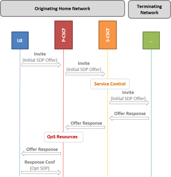
- Initially, the UE sends a SIP message like ‘Invite’, containing the description of one or more measures for the voice session (Initial SDP - Session Description Protocol - Offer).
- Then the P-CSCF forwards this same message to the S-CSCF (which has been identified during the registration process).
- All going well, the termination network will have sent a message of type ‘offer response’ to the S-CSCF, and this sends this message to the P-CSCF, authorizing the allocation of the resources necessary for this session.
- Finally, the P-CSCF forwards the ‘offer response’ message back to the UE, which confirms the receipt of the ‘offer response’ message and the resource reservation is started.
This is a very simplified example of how you can be getting (origination) of a voice service by the UE, via IMS.
Several other diagrams exist, with far more complex scenarios, but the basic idea can be seen above, and extended if necessary.
Let’s complete the tutorial today, now seeing the case where an initially established call on IMS has to be ‘transferred’.
SRVCC
Finally we come to our last alternative listed at the beginning of this tutorial: SRVCC (Single Radio Voice Call Continuity).
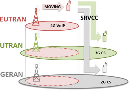
The SRVCC however is not an alternative for delivery, but a rather a handover process of a voice call previously started in the LTE (whether One Voice - VoLTE LTE or IMS Full Voice).
It is a call transfer method (handover), in a simplified and reliably way, when an LTE user has an active voice session in IMS and is moving to areas without LTE coverage, but with legacy 2G/3G coverage.
The main advantage is that the call will not drop - will only be transferred to the CS domain of the legacy networks.
If in the above case the UE moves out of LTE coverage area with an active call (but goes to a legacy 2G/3G coverage), we must maintain the continuity of this active voice call. In this case, the SRVCC is used: the procedure where the context of an active voice call on the IMS is transferred to the CS legacy network (e.g. IMS node context transfer to the MSC).
The challenge with SRVCC is to perform the handover while the UE is connected to only a single radio at any given moment.
There are two versions of SRVCC:
- SRVCC handover to GSM or UMTS, defined by 3GPP;
- SRVCC Handover to 1xRTT networks defined by the 3GPP2.
To allow SRVCC both the UE and LTE networks, as also the legacy, must support SRVCC. For this, a new special SV interface is introduced between the MME and the MSC, which runs on GTPv2 protocol.
To support SRVCC, the IMS network should also include an application server, called SCC AS (Server Centralization and Continuity Application Server).
This application server is who manages the signaling required for the process.
Let’s see a simplified example of some SRVCC procedures from LTE to GSM.
- When an UE that supports VoLTE is in an LTE coverage area, it starts voice sessions via the IMS network, which will host the session and provide applications and session control based on SIP.
- When the UE moves from an LTE coverage area for a CS 2G/3G coverage area, with the active IMS session, the IMS switches the session to the CS domain, maintaining both parts aware of the handover session.
Example of SRVCC Handover
Realizing that its LTE signal level begins to decrease, the UE with an active IMS voice session signals it to the eNodeB, initiating the SRVCC handover.
The eNodeB then identifies the best available network to receive the service, and sends the handover request (specifying that it is the SRVCC type) to the MME.
The new voice call request is then sent to the IMS, using a SR STN (Session Transfer Number for SRVCC) - a unique number that is generated by each UE, and is stored in HSS.
This unique number is sent by the MME to the HSS when the UE firts comes into contact with the network.
Upon receiving the STN SR number, the SCC AS believes that the corresponding call should be transferred to a different network network, and starts the redirecting process for the transfer point (handover) to the legacy network.
After resource preparation is completed, the MME confirms the handover request, previously provided by the eNodeB.
The eNodeB then transmits this acknowledgment to the UE, while still providing the required information about the target network.
In the final stages, the UE is detected in legacy networks, and the call is re-established in it.
Thus we have the completion of the SRVCC handover.
Voice packets and also packets that are not voice can be transferred using this method, but the data rates will be limited by the capabilities of the legacy networks.
Once the SRVCC is a procedure for inter-RAT handover based on IMS LTE network to the CS legacy network 2G/3G, it is much more complex than that of handovers legacy networks 3G / 2G. The question is how to maintain a handover performance comparable to or better acceptable.
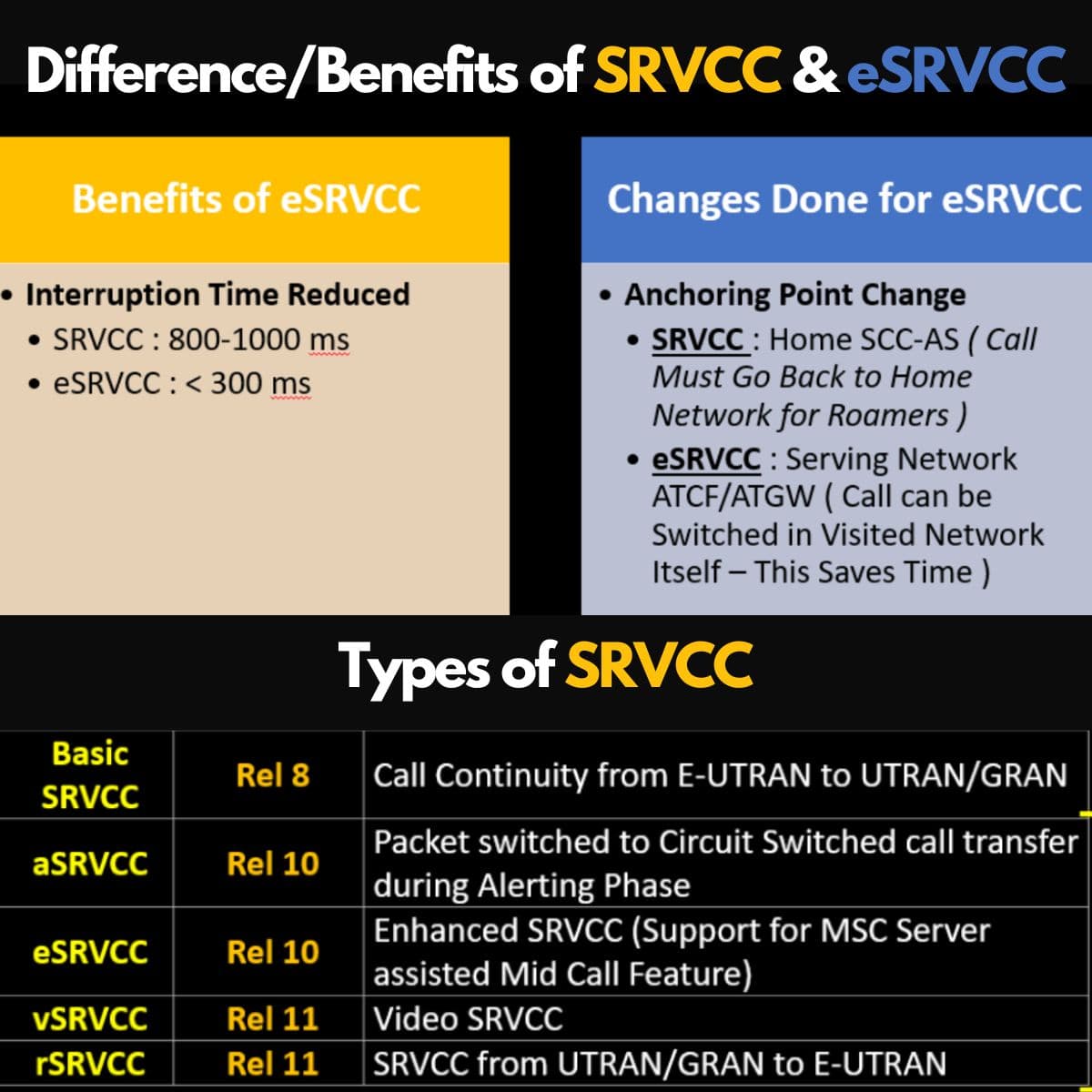
In order to improve the performance of the SRVCC handover, one WI (Work Item) called eSRVCC (SRVCC enhancement) was established in the 3GPP SA2 in Release 10. The anchoring solution is based on the IMS, and introduces new entities ATCF (Transfer Control Access Function ) and ATGW (Transfer Access Gateway).
Again, the deepening of this subject escapes from our goal today.
Finally, we will enumerate some of the main advantages and disadvantages (or pros and cons) of each alternative.
Advantages and disadvantages of each alternative
Call setup time : When operators use CSFB, one of the biggest problems faced (and one of the major disadvantages of CSFB) is the increase in call setup time due to retuning procedures in 2G/3G radios.
An efficient CSFB solution requires the the TAC → LAC mapping is so that the fallback to an external MSC/LAC be avoided, since this will further increase the call setup time.
Call quality : call quality in LTE is better when compared with the same third-party applications (OTT). This is due to specific QoS allocated to the call IMS, which may not be present in common data applications.
Resource limitations for VoLTE : AMR-NW LTE requires much less resources and datarate than GSM, and we will have many more users on the same bandwidth (spectral efficiency).
Investment x Current Network : if everything is ‘working well’, what would be the reason for investment, since surely such investments generate resistance from commercial and business areas?
The comparison that must be done is: Investment versus (all) Benefits of IMS/MGW/BGCF.
Future: In any way all that discussion hereafter will more significance. Currently we still have extensive legacy networks, capable of supporting these voice calls.
In this case, it is no problem to continue using this available infrastructure. Resistance will only decrease when such capacity also decrease. But in an LTE network, if the IMS is supported can make a VoIP call. So why would we need to make a CS voice call?
CSFB x SRVCC :
- It is not necessary to implement both solutions (CSFB and SRVCC) at the same time, if the network has a wide LTE coverage and a complete IMS backbone.
- If we implemente CSFB, it means we will not make the call setup using existing IMS Core, and that could take care of that call in LTE.
- In respect to the SRVCC: assuming the Backbone IMS is available. In this case, if the register in the IMS is successful, the user do not need to do CSFB - A voice call can be simply initiated in LTE network using IMS.
- CSFB is a service handover procedure while SRVCC is a coverage handover procedure.
Case Studies and Analogies
With all that we have seen today, let’s imagine some scenarios.
First, imagine that you are in a network that does not have LTE IMS. Then the only way to make a voice call, whether originated or terminated, is through using legacy 2G/3G.
You need to be redirected/released from LTE to legacy 2G/3G network to make a voice call. Like a ‘reselection’ from cell LTE to the 2G/3G. Once the legacy network, you can make the call normally, as you’re already used to.
And so, you just saw the CSFB in practice!
Now suppose you are watching a video stream on 4G network, and receive a voice call. In this case, you need to go to the 3G network (in idle mode), and get the resources for to make that call in 3G.
After you end your voice call, you keep watching the video stream, but now in the 3G network (the handover from 3G to 4G is not yet defined).
You just saw the CSFB with an active data call!
Now let’s imagine that you are in another LTE network, this time with IMS. In this case, you can make a voice call using IP packets.
We have just seen a VoLTE call!
Further, imagine that you are in one of these voice calls using packets in 4G. Suppose further you reach your 4G cell coverage edge. So the only option to keep your call is to handover it to the 3G (assuming this is the existing coverage). Your call will then continue on the 3G network, but now as one CS voice call. SRVCC!
If the SRVCC is not supported, the call is dropped as soon as it leaves the LTE coverage area.
If the SRVCC is supported, a set of messages are exchanged, and the voice call is transferred (handover) from LTE IMS to CS domain of the 2G/3G network.
And so, we have just seen an example of SRVCC handover!
And that’s all for today. We hope that the tutorial has managed to be useful for you that somehow are interested voice in LTE networks.
Conclusion
We saw in this tutorial today, in a very general way, the main ways to make voice calls (and SMS) in LTE networks.
The options or alternatives depend on several factors, such as available network topology and the operator’s strategy.
Depending on the situation, the call can be originated in LTE via data applications (OTT VoIP), be purely originated on LTE IMS (VoLTE), sent to be performed on other networks through mechanisms developed for this purpose (CSFB) or transferred via handover - if active VoLTE call - to a legacy network (SRVCC).
So, for a user who is a LTE coverage area, a number of considerations should be checked, as the type of device that it uses (whether supports CSFB), if the LTE network has an IMS that allows outgoing calls, if the cells supports SRVCC, etc.
Based on the concepts seen here today, we hope you have a position to fully understand what happens when a user performs a voice call from an LTE network.