Introduction
If we only talk about the “device”, you’ll probably know how to define what is an antenna, or at least you have ever seen one. We also know that changing conditions or characteristics, for example targeting them, they improve the communication link.
But if someone ask you to describe what is an antenna “technically speaking”, how would you describe how it works?
That’s what we’ll talk about today.

Basics
Before we begin to define how an antenna works, we need to learn (or remember) some basic concepts.
By understanding these concepts, it will be much easier to understand how antennas works.
Wavelength
Radio waves (electromagnetic) are physical, of which we highlight the frequency. We know it is not easy viewing.
So let’s make our first analogy: imagine a drop of water falling on the flat surface of a bucket of water.

After the droplet hits the water at rest, we can see the waves formed.
In telecom we specifically describe the pattern of sine waves, the wavelength is distance between two peaks.
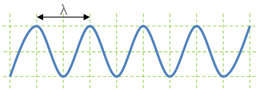
Mathematically, the wavelength (λ) is defined by the speed with which the wave propagates (c) divided by frequency (f) thereof.
λ = c / f
- wavelength (λ): is represented by the Greek letter λ;
- speed (c): Considering that our waves propagate in air, we can consider as the speed of light in vacuum - c - 300,000,000 m / s (which may be represented by 300M m / s);
- frequency (f): frequency of the signal will be using.
For example, on a 900 MHz system, we have: λ = (300 Mm / s) / (900 MHz) = 0.33333 … or 33.33 cm .
Polarization
When we talk about electromagnetic waves, another important concept is the polarization, ie what the plan of the electrical component in which the wave propagates.
Ok, started to complicate things? So let’s try to explain better.
Electromagnetic waves are composed of two planes - vertical and horizontal. These plans represent the electric and magnetic fields. These components are always orthogonal, vectors off by 90 degrees. They vary in phase - or zero - degrees of electrical phase shift.
The propagating speed (also vector) for these two fields in turn spreads in 90 degrees of the two.
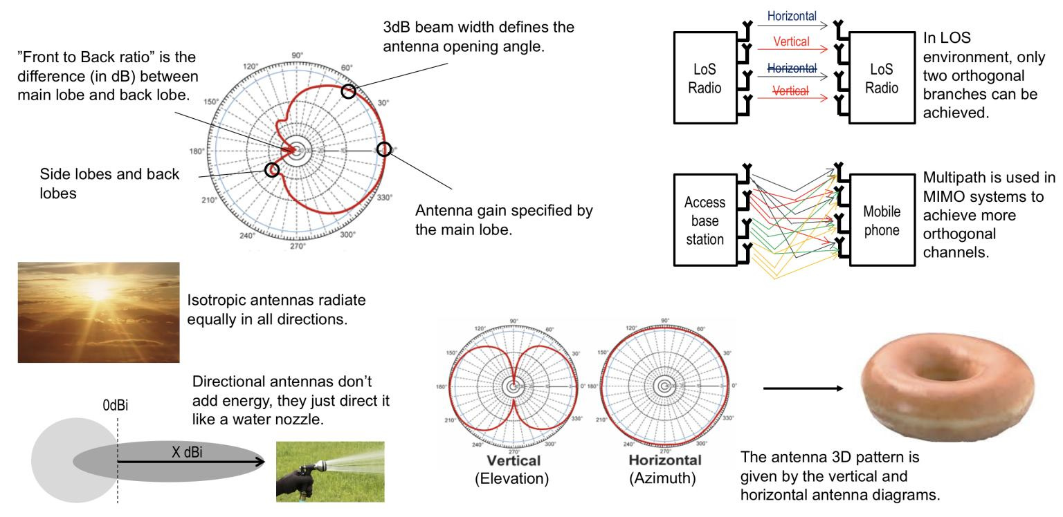
The following figure helps us visualize these vectors.
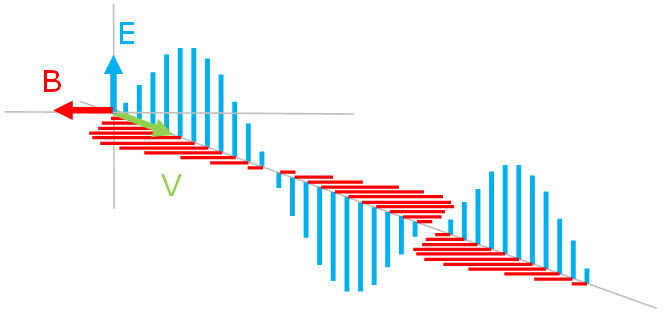
So depending on how the signal coupling is done - the antenna is oriented - we have a definition of polarization.
If the transmitter is such that the wave is completely in the vertical plane (Electrical plane E), then we have Vertical polarization. If the wave is in the horizontal plane (Magnetic plane B), we have Horizontal polarization. There are other types of polarization, as Cross polarization and Circular polarization (right and left), that actually are combinations of vertical and horizontal polarizations, and also the phase differences.
The concept of polarization is very important in antennas, mainly because when a signal is transmitted in one polarization must be received in the same polarization, otherwise we will have an attenuation (loss), known as cross-polarization.
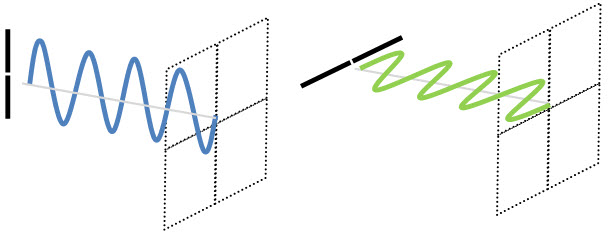
To better understand the polarization of waves, let’s see some examples, in which we highlight only the E component - electric field. (Remember though that there are always a magnetic field 90 degrees to the electric field).
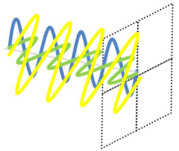
And see how looks the wave (the electric component E) for Cross polarization - a combination of vertical and horizontal polarizations, electrically in phase.
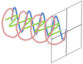
Let’s stop here, our artistic ability (?!?) limits us! But a wave with Circular polarization (electric component E) - a combination of two polarized waves - one vertical and one horizontal, electrically out of phase by 90 degrees, but with the same magnitude, it would “more or less” as we draw down. Surely the real wave is at least less “shaky.”
As an example of antenna with Circular polarization we have Helical Antennas or Cross Yagi with Circular polarization (left or right), better known as RHCP (Right Hand Circular Polarization) and LHCP (Left Hand Circular Polarization). We’ll see more of their applications in due course.
Antennas
Okay, after briefly introducing some basic concepts, let’s talk about antennas.
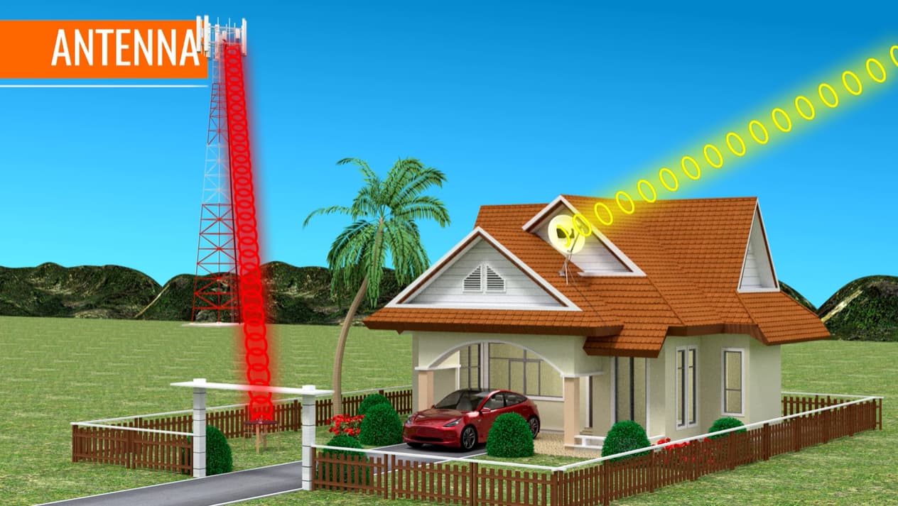
By definition, an antenna is a device designed to transmit or receive electromagnetic energy, matching these sources of energy and the space. Also often called radiant systems. Note that the same device can be used to transmit or receive.
Let’s start by looking at a simplified representation of a system for transmission and reception.
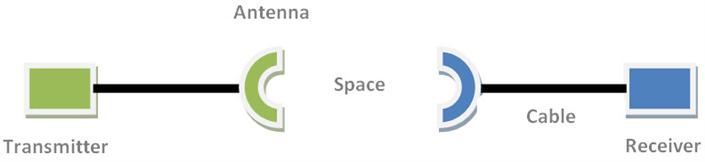
The original information is changed, for example through some kind of modulation and treatment, and still conveyed or guided by a cable to the antenna. The antenna then radiates this information by the medium (air) until it reaches the other antenna, which in this case will make receiving the signal, making it still the way the cable to the device that will make such demodulation (and other treatments), recovering the original information. Note: Just as an example, we are not considering existing losses.
Sure, but how the antenna works? How she radiates the information?
To understand this, we need a little atomic review!
Calm down, let’s just talk about atoms: Atoms are the smallest possible share of any chemical element. All that exists is made up of elements.
Put simply, most of them are formed by the atoms: protons, electrons and neutrons. At the core of the atom have the neutrons and protons. The electrons stay moving around this nucleus, like cars on a trajectory as in a crazy race.

An attraction (positive-negative) is what makes it possible that all elements exist.

But what does this have to do with the antenna?
The antennas are usually made with metallic materials (aluminum / brass). These metals are formed by atoms. When all the atoms are brought together - to form the metal, then we have a set of free electrons.
And when this series of free electrons is subjected to an electric voltage (electric field), they begin to move and vibrate.
When electrons vibrate from one side to another antenna, they create an electromagnetic radiation in the form of radio waves.
Pause: Are You caughting up how energy is radiated by the antenna?
Well then you’ve got it all. Because now, just the opposite happens.
The electromagnetic radio waves that leave the transmitting antenna travel through the medium, eg air, and reach the other antenna - reception. The effect of electromagnetic field reaching the other antenna is to make the free electrons vibrate in the same - which now generates an electric current corresponding to what was sent from the transmitting antenna.
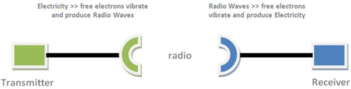
So now we can conclude: the transmission antennas convert the electrical current ( electrons ) into electromagnetic waves ( photons ), and the reception do the reverse - convert electromagnetic waves ( photons ) into electrical current ( electrons ).
The information is preserved because the antenna acts as a transducer matching conductors that generate these fields. For example in the transmission, the electromagnetic field corresponds to a specific voltage and alternating current. In the reception, the same reference voltage and alternating current is induced.
A Simple Antenna
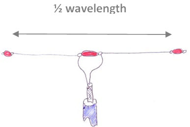
Further, consider the representation of the simplest type of antenna: a dipole antenna. As the name suggests, is an antenna with two poles.
It is a model of the antenna easy to make, and consists of two pieces of wire of equal length, separated from each other by a center insulator and may have an insulator on each end to attach it to a support.
In the figure below is an example of a dipole antenna (insulators shown in red in figure).
Let’s use this example to talk about antennas, but now we’re basically with simple question, but that many people can NOT explain:
“How can there be a current flowing in antenna, if both parts are open? This runs totally against what we learn, where have current, we need a closed circuit, no?”
To answer this, we again return to the familiar concepts of electrical circuits.
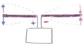
You must remember the concept of capacitance (C), defined through the use of capacitors. And there is a kind of unavoidable capacitance that arises between compontent always close to each other on the circuit - and often unwanted: parasitic capacitance.
Only in our case, this capacitance is what allows the antenna to work!
At high frequency, the parasitic capacitance between the two arms of the antenna has a low impedance, and represents the current return path.
In short: a tuned antenna can be considered as an RLC circuit - with resistance R, inductance (L) and capacitance (C)!

It’s beginning to be clear?
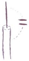
Note: You may wonder: “And in the case of antennas with only one arm?” Do not worry, the antenna will always seek a reference plane to act as “ground”, such as a metal rod next.
From what was shown, we can say that every antenna requires two parts to radiate energy. And that energy is proportional to the dipole current.
Okay so far? After many pauses for further explanations, let’s continue talking about further concepts.
Resonance
Recalling what we have seen so far, the electric waves in antennas usually have a fixed wavelength.
We also saw that an antenna can be considered as an RLC circuit, where definition of these features are given by the environment where the antennas are, and their physical properties - especially its size.
Ready for another term? So here we go: Resonance!
In general, resonance is the phenomenon that occurs in a particular frequency where we have a maximum possible transfer of energy .
In the case of antennas, so there to be resonance, its size (physical length) must be a multiple of its wavelength. In this case, we will have a main frequency where the antenna delivers the maximum amount of energy possible - resonant. And the larger the size (length) of elements of the antenna, the lower the resonant frequency .
In more technical terms, we have the resonance frequency where the inductive and capacitive reactances cancel each other out - we have a purely resistive impedance.
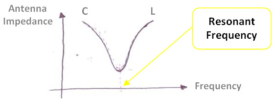
Most antennas are used in its resonance frequency. That’s because when we turn from this resonance frequency, the reactances levels give rise to parameters that may jeopardize the operation, for example the SWR, as explained in another tutorial. The impedance of the antenna ceases to be purely resistive, with a complex impedance - in both meaning of the word, which gets her an unwanted behavior.
It is clear that a non-resonant antenna also works - transmit and receive. But it needs a more powerful transmitter (because a smaller part of the input energy will be present at the output). And for the same reason, you need a receiver with a sensitivity much higher. So: the system efficiency will be much lower!
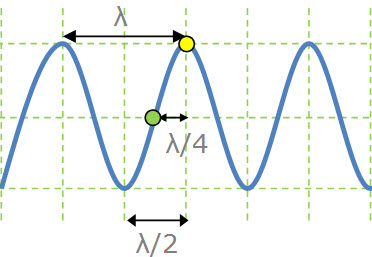
Wavelength X Length of Antenna
Just to finish by today, you should remember what we taught to be the resonance of the antenna physical size must be multiple of its wavelength.
Let’s try to understand why exactly this value? As always, let’s remember more concepts…
Remember that an electrical circuit - which we has also mentioned that a tuned antenna acts as an RLC circuit - the Voltage (Potential Difference):
- in a Short Circuit is equal to Zero ;
- in an Open Circuit is Maximum .
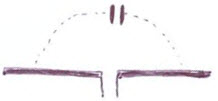
Well, the antenna end, we have an Open Circuit - so the point with the Highest Voltage.
And considering the two ends - one with the maximum positive voltage and one with the maximum negative voltage - we have the center point with Zero voltage.
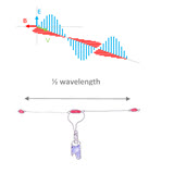
This distance between the end and the central point is the distance between the point of maximum voltage (yellow circle in figure) and point of zero voltage (green circle in figure) - and is a quarter wavelength !
Properties and Types of Antennas
After our brief summary, focused mainly on the functioning of the antennas, we can proceed with several other concepts, types of antennas, etc..
Some concepts - for example Impedance - were also mentioned, but were not well described.
But for today, our tutorial is already extended too much , and is also very difficult to absorb more knowledge than what was exposed here, at once. So lets take this supplement ,as well as continuing the subject of antennas, for the next tutorials. Much remains to be said, many questions to be eliminated.
Hopefully you have managed to understand at least some of the basics of antennas.
Now, do you have a minute?
Before we finish, and IF you liked the article, or other articles in telecomHall, we would like to make just one request, is it okay?

With a simple gesture, you can help us to improve more and more, bringing each week tips, tools, tutorials and everiything more that really are worth reading for Telecom & IT.
So, we would ask to help us simply by sharing with your friends. To facilitate it, follows links that let you do this quickly and easily :
We will be very happy with your participation. Thank you, really!
Conclusion
Today we had a first approach on antenna, an undeniably important subject, and a essential system for the good performance of any network.
As always in a more informal way, we try to flow explanations in a simplified manner, as a matter of course is a foundation for other studies and further refinements as necessary.