Hi Experts.
Please help to decode this table:
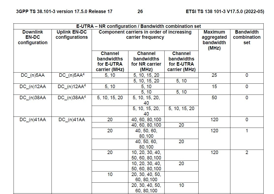
Note: taken from this spec: https://www.etsi.org/deliver/etsi_ts/138100_138199/13810103/17.05.00_60/ts_13810103v170500p.pdf
Hi Experts.
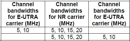
Please help to decode this table:
Note: taken from this spec: https://www.etsi.org/deliver/etsi_ts/138100_138199/13810103/17.05.00_60/ts_13810103v170500p.pdf
I think it’s related to the combination of bandwidth when using 5G NSA.
You are right DC_(n)5AA means DC_(n)5AA means NR n5 band and LTE band 5 combination.
I am trying to understand column 2, 3 and 4.
What does this info mean, the upper row is for DL or Uplink and vice versa?
There are two rows for each BCS, how to interpret it?
These are the MHz combination possibilities.
Yes, but how to conclude upper row is for Downlink or Uplink?
LTE Band 5 is a FDD band. It always has symmetrical uplink/downlink spectrum.
I don’t see any indication that this is being changed here. So you should not assume that those two rows indicate different Uplink/Downlink combinations. My guess is that the only difference between the two rows is the order: LTE-NR or NR-LTE.
As I can see, it is not explicitly mentioned in the 3GPP the exact definition of each column, but as per my understanding:
And I think column 2 and 4 are almost the same for all band combinations.
This video explains part of how to read such UE capabilities combinations from UE logs and 3GPP, but it didn’t cover the part you asked for but it has other similar examples.