One of the biggest lessons in RF Optimization is that improving one KPI can sometimes impact another.
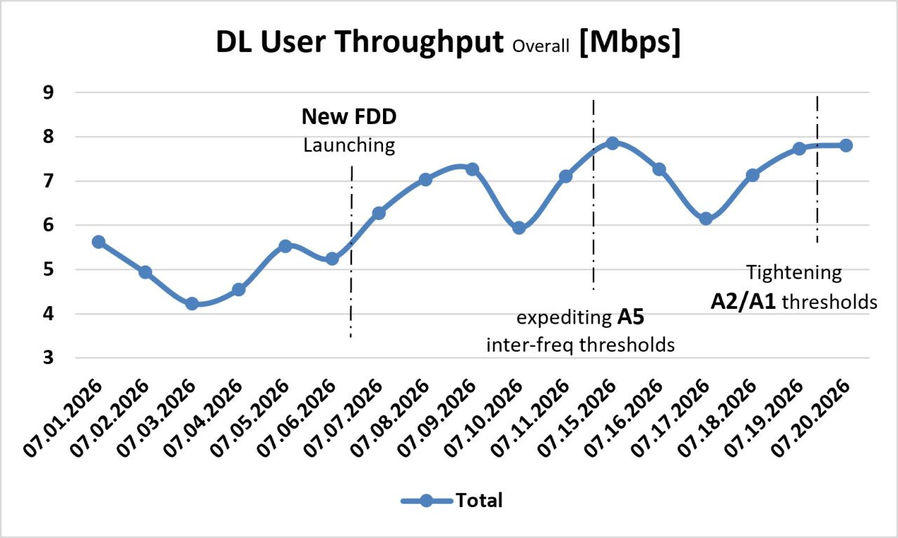
In one project, the network consisted of two LTE TDD carriers and one LTE FDD carrier. After deploying a second FDD carrier, data and VoLTE KPIs improved significantly, but the customer expected even higher overall DL throughput and fewer low-throughput cells.
Since Load Balancing Handover was already active, we fine-tuned the A5 handover thresholds between the new FDD carrier and the two TDD carriers to improve traffic distribution across the layers. The result was exactly what we wanted—higher throughput and the customer’s target was achieved.
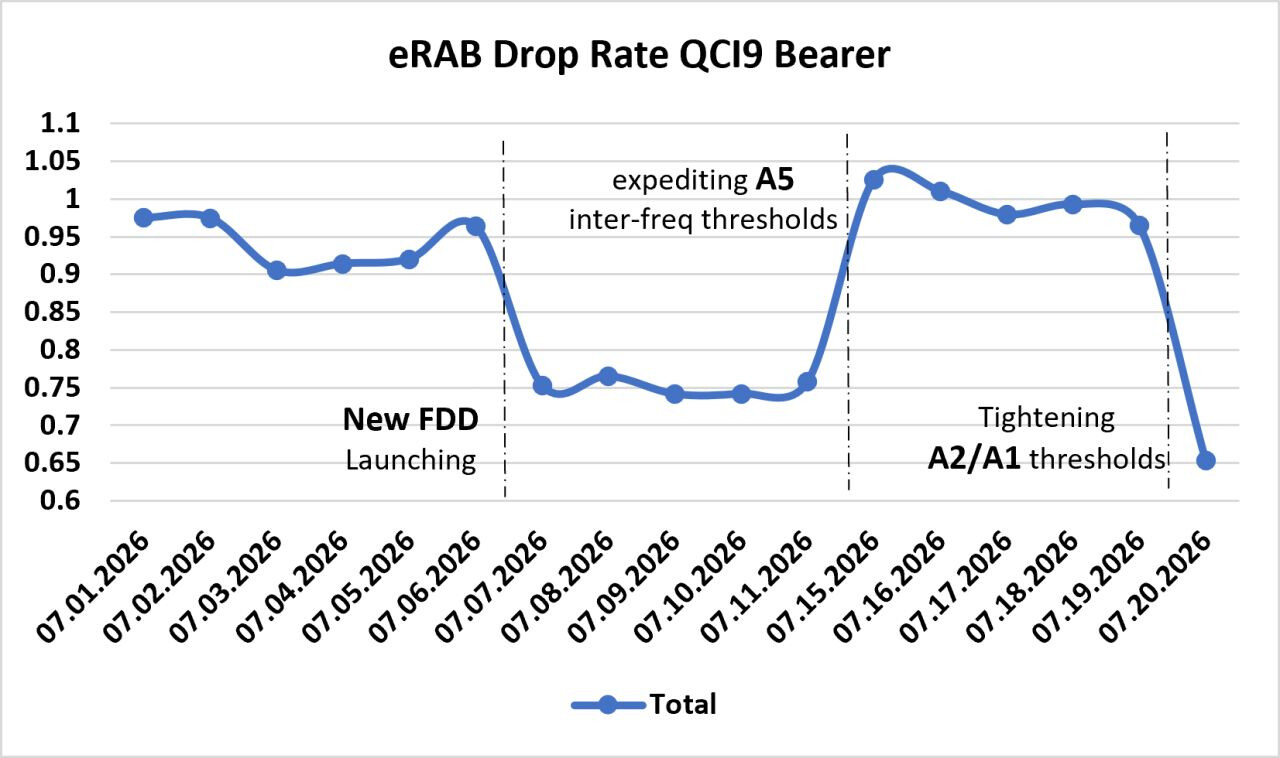
However, another KPI started to degrade: E-RAB Drop Rate for QCI 9 bearers.
After investigating the interaction between A1, A2, A3, A5, and Load Balancing Handover Parameters, we found that the root cause was not the A5 optimization itself, but an overly relaxed A2 threshold on the original FDD carrier. Fine-tuning the A2 threshold restored the E-RAB Drop KPI while preserving all the throughput gains.
This case was a great reminder that RF Optimization is not about improving a single KPI—it’s about understanding how parameters interact and finding the right balance between capacity, mobility, and user experience.
That’s what it means to be an RF Optimization Engineer.
This post highlights the key stages of the optimization journey. Behind these results were numerous technical investigations, KPI analyses and stratigies validations, that are beyond the scope of a single LinkedIn post.
LinkedIn: 