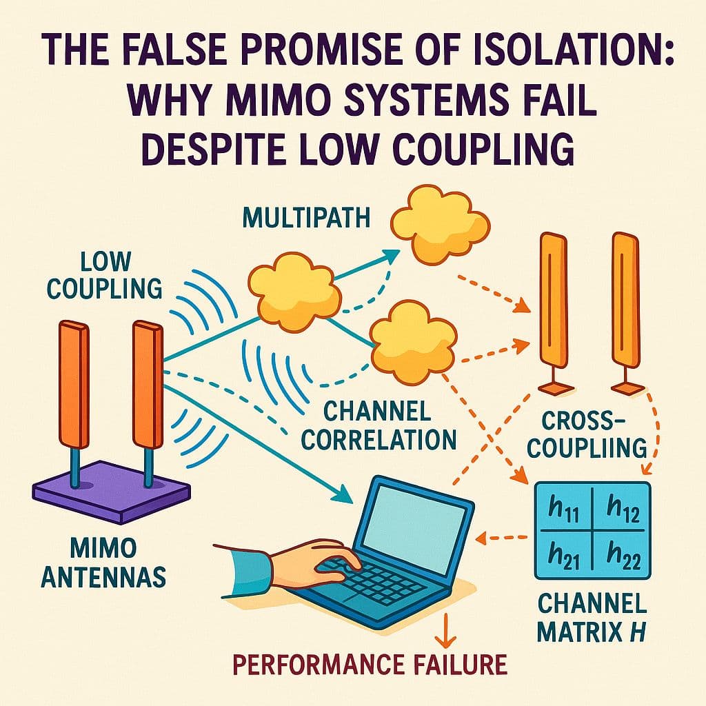
You measure S₁₂ nice and low, isolation looks great but on air the throughput crashes. Why? Because low coupling doesn’t mean real independence. MIMO fails when patterns overlap even if ports seem separate.
1. What Isolation Actually Means:
Isolation in MIMO typically refers to how much power leaks between ports, quantified by S₁₂ or S₂₁. If this number is low, we assume the antennas won’t interfere with each other. But this is only port level decoupling not field level separation. You might have -25 dB isolation at the VNA but if the antennas still radiate into the same spatial mode or direction, your MIMO system’s diversity benefit is lost. It’s like singing two songs in harmony but through the same speaker.
2. Why Low Coupling Doesn’t Equal High Performance?
MIMO capacity hinges on orthogonality not just in frequency or polarization but in space, if two antennas produce similar radiation patterns especially in compact systems, the receiver can’t distinguish them well even if their ports seem “isolated.” This leads to high correlation, interference and reduced rank in the MIMO channel matrix. What’s worse! overly aggressive decoupling networks might suppress power transfer and ruin efficiency.
3. How Mutual Coupling Hides Behind Low S-Params?
Even with low S₁₂, coupling effects can reappear in other forms like pattern distortion, near-field re-radiation and shared surface currents. For instance, a patch array might show perfect isolation in anechoic test setups but fail under real environments with human loading or reflective surfaces. This is why system level validation, including Envelope Correlation Coefficient (ECC) and Total Active Reflection Coefficient (TARC) is more meaningful than S-params alone.
4. Critical Formulas:
-
Mutual Coupling (S-parameter based):
→ Isolation = |S₂₁|² -
ECC from far-field patterns:
→ ECC ≈ |∬ F₁(θ,φ)·F₂*(θ,φ) dΩ|² / (∬|F₁|² dΩ · ∬|F₂|² dΩ) -
TARC:
→ TARC = √(Σ|bₙ|²) / √(Σ|aₙ|²)
where aₙ and bₙ are incident and reflected waves -
Channel Capacity (simplified MIMO):
→ C = log₂[det(I + ρ·HHᴴ)]
where H is the channel matrix
5. Real-World Examples:
- A smartphone with 4x4 MIMO antennas placed closely shows low S₁₂ values but strong correlation due to near-identical patterns, hurting spatial multiplexing gains.
- A base station panel with hybrid fed dipoles achieves excellent isolation but real world wet weather conditions create surface wave re-coupling paths, reducing user capacity.
- A wearable MIMO system using monopoles detunes near the body despite good bench S₁₁/S₁₂ and ECC increases beyond 0.6, limiting diversity performance.
- A Wi-Fi router’s antenna array shows great port isolation but points all beams in the same direction due to reflective enclosure design, defeating MU-MIMO benefits.
LinkedIn: ![]()