Hi guys,
Anybody know how exactly testing MIMO 5G beamforming funtionality working in the field and how we can prove it through field results?
Do a Drive Test 120 degree H and 30 degree V and see if you have good throughput from same PCI.
Rsrp should not decrease by more than 3 dB within the grid of beams that is 120H and 30V.
Assuming there is line of sight all the way SSB RSRP should not decrease in average more than 3dB.
1 Like
Which feedbacks can prove this in logfile?
SS RSRP will give you the coverage of the cell/PCI.
Does we have something on TEMS to check for beam indexes?
How we would know if really beamforming of 16 or 64 ports is working?
Yes, You can check it from L3 rrc reconfig msg -> ssb-positionsInBurst.
Total 8 bits for sub6 Ghz, each bit represent one ssb id.
Or from L1 serving beam management will show the serving beam with its detected beams.
You may check for PCI -SSB ID combinations.
The number of SsB Ids for each sector (small cell) 8 ,64 etc gives the number of SS beams for the 5G cell, which will be synched after beam tracking beam sweeping etc
If Qualcomm chipset UE is used you will get these from Qualcomm tree.
Ctrsy : Xcap
Brother,
hope this will be helpful for you
Below is the rrc-reconfig message where you will find no.of SSB beams in SSB burst
ssb-PositionsInBurst : mediumBitmap
mediumBitmap : 10000000
[0 ] : 1
[1 ] : 0
[2 ] : 0
[3 ] : 0
[4 ] : 0
[5 ] : 0
[6 ] : 0
[7 ] : 0
For No of ports used by the UE, based on the UE capability, like
If the UE capability includes a configured CSI-RS(maxConfigNumberPortsAcrossNZP-CSI-RS-PerCC 16, example from the UE capability info) it gets configured to use the highest number of port supported. For example: 4, 8 and 32 ports configured in cell, here UE capability supports up to 16 ports. In this case, UE should get 8 port configuration.
Check csi-MeasConfig from rrc-reconfig message you will find the details about it.
For your information
Just check nzp-CSI-RS-ResourceToAddModList in this Resourcetoaddmodlist, we have resource id mappings like nzp-CSI-RS-ResourceId(from 0 to 3 its TRS info, as we define TRS using the CSI-RS resources) and also check nzp-CSI-RS-ResourceId 4 is exits for NZP CSI-RS where you will get the configured no of ports.
example from rrc-reconfig
nzp-CSI-RS-ResourceId : 4
resourceMapping
frequencyDomainAllocation : other
other : 000011
[0 ] : 0
[1 ] : 0
[2 ] : 0
[3 ] : 0
[4 ] : 1
[5 ] : 1
nrofPorts : p8
firstOFDMSymbolInTimeDomain : 5
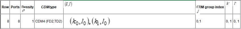
cdm-Type : cdm4-FD2-TD2
density : one
You can match the above with TS38.211 Table 7.4.1.5.3-1 CSI-RS antenna ports, density in frequency and CDM type table.
3 Likes
Hello @Ameen i need to enable max number or TRS for FR2 by so the number of configured TRS resource sets per CC is determined by related UE capability (this as NW config),
which parameter exactly from UE capability show the capability ? also how can i verify from RRC reconfiguration ? which parameter
thanks
Dear,
As far as i no, 1 slot is supported only, for >6GHz (Reason for this might be due to shorter Slot durations for higher SCSs in NR)
which parameter exactly from UE capability show the capability ?
UE capability with CSI-RS for TRS related configuration:
csi-RS-ForTracking
Indicates support of CSI-RS for tracking (i.e. TRS). This capability signalling
comprises the following parameters:
- maxBurstLength indicates the TRS burst length. Value 1 indicates 1 slot and value 2 indicates both of 1 slot and 2 slots. In Latest release UE is mandated to report value 2;
- maxSimultaneousResourceSetsPerCC indicates the maximum number of TRS resource sets per CC which the UE can track simultaneously;
- maxConfiguredResourceSetsPerCC indicates the maximum number of TRS resource sets configured to UE per CC. It is mandated to report at least 8 for FR1 and 16 for FR2;
- maxConfiguredResourceSetsAllCC indicates the maximum number of TRS resource sets configured to UE across CCs. It is mandated to report at least 16 for FR1 and 32 for FR2.
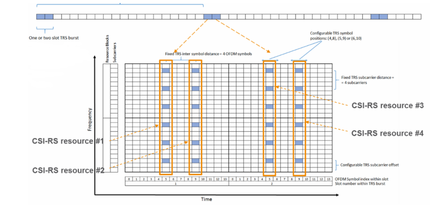
Below figure shows how TRS resources are configured within Resources set.
In RRC re-configuration Message, here you can find the TRS information(TRS-Info: true)
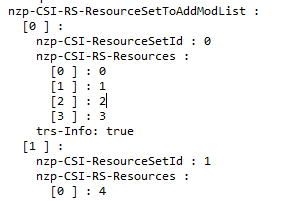
above RRC message, We have Resource set 0 and 1 configuration for TRS and NZP CSI-RS. It means Resource set 0 is for TRS and resource set 1 is for NZP CSI-RS.
All the above resources configuration can be found in csi-MeasConfig in the same RRC Re-configuration message.
Points to remember always about CSI-RS TRS:
Slot level
The UE may be configured with a CSI-RS resource set of four CSI-RS resources in two consecutive slots with two CSI-RS resources in each slot, i.e. four CSI-RS resources within one CSI-RS resource set.
The CSI-RS resource could be periodic or aperiodic. currently only periodic is supported and the CSI-RS resources in the CSI-RS resource set should have the same periodicity, bandwidth and subcarrier location.
i.e. the two slots should have the same pattern.
Symbol level
The OFDM symbol indices for each CSI-RS resource in a slot is given by one of (4,8), (5,9) or (6,10). Currently only (4,8) is used in our product(vendor specific)
.
TRS/CSI-RS cannot be transmitted in a slot where RMSI and SSB is transmitted.
all the above points are clear when you check above picture and rrc message.
Hope this will help you.
2 Likes
Yes Ameen , Appreciate your reply
thanks a lot
Hi Ameen, thanks for the good info. I have one more question, what actually UE decodes via TRS slot and how that helps UE oscilator to stay tune in time and frequency? also how it does help doppler and delay spread estimations.
Thanks
Thanks appreciated