RAN Protocol Stack
NOTE : All images are copyrighted material. We have use them here, only for fair purpose. No Copyright-Infringement intended.
Lets have a look on Ran Protocol Stack.
We have seen from the above image that there are two types of RAN Protocol Stack:
- User-Plane Protocol Stack
- Control-Plane Protocol Stack
Each layer which are shown in the diagram uses the information from the below layer and provides services to the above layer. (Both in User Plane and Control Plane Protocol Stack).
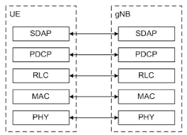
In User Plane Protocol Stack information is communicate between the User Equipment (UE) and gNB( 5G RAN).
RAN-Random Access Network.
In Control Plane Protocol Stack information is communicate between the User Equipment and gNB and the Core-network.
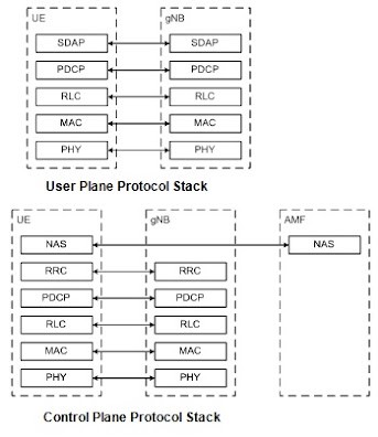
First Discuss about the layers of User-Plane Protocol Stack
- SDAP ( Service Data Adaptation Protocol ) — This layer is responsible for QoS (Quality Of Service) Flow Handling .
- PDCP ( Packet Data Convergence Protocol ) — This layer is responsible for Header Compression,In Sequence Delivery, Ciphering and Integrity Protection, Transfer of User plane as well as Control plane data, Removal of Duplicates.This Layer also, Routing the split barriers .
Due To Header Compression Functionality, it is called Convergence Protocol.
- RLC ( Radio Link Control ) — This layer is responsible for Segmentation and ARQ(Automatic Repeat Request) for Error Correction (only for AM data Transfer ). AM here means Acknowledge mode of data transfer.We will talk about this in deep in Part-2 of this series.
- MAC ( Medium Access Control ) — Mapping of information between Logic and Transport Channels, Scheduling , Multiplexing and Demultiplexing , Retransmission of data.
- PHY ( Physical Layer ) — This layer is responsible for efficient communication over the network.This Layer has many works describing by the below image. We will see this layer in detail in subsequent parts.
Now we have discuss about the layers of User Plane , as we can see that all layers of User Plane are same as Control Plane except the RRC and NAS.
So we are only doing RRC and NAS for Control Plane as left layers are already covered in User Plane .
- RRC ( Radio Resource Control ) — This layer responsible for Connections establishment and release functions, broadcast of system information,radio bearer establishment ,reconfigurations and release.
- NAS ( Non- Access Stratum )- This layer is responsible for authentication Security, Mobility Management , Call control Management ,Session and Identity Management , Idle Mode Enabling (Paging).
In the below image, we have all layers of User Plane Protocol Stack . Now From top to bottom, we will go through each layer with wide description of each functions within each layer.
source — techplayon.com
- SDAP ( Service Data Adaptation Protocol ):
Functions of this layer are :
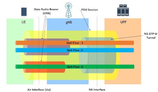
- QoS ( Quality of Service ) Flow Handling : This layer mapped the quality of service , QFI (Quality of Service Flow ID) to the appropriate radio bearer between the gNodeB (RAN) and the UE (User Equipment or Device).
QFI(Quality of Service Flow ID): It is used to differentiate between different quality of service within the PDU’s (Protocol Data Unit) Sessions.
Below Image give you the overview about what we describe above.
source — techplayon.com
As you can see that QoS Flow are giving their QFI for differentiate between different quality of service within a PDU Session.
All Quality of service are grouped together in a GTP-U N3 tunnel which is between the gNodeB (RAN) and the UPF(User Plane Function).
Now , you can see in the above image that QFI -1 and QFI — 2 is mapped within the same radio bearer, as it is the works of SDAP.
If one QFI is for whatsapp video call and another QfI is for zoom video call so SDAP mapped these QFI in the same Radio Bearer and other QFI such that Youtube Videos such that live streaming than it mapped this is different Radio Bearer.In some Cases , there will be different PDU Session also .
Now we have three different types of Quality of Service :
- GBR(Guaranteed Bit Rate) : This is defined for the applications which required Guaranteed Bit rate .
- Non-GBR(Non Guaranteed Bit Rate): This is where traffic is bursty in nature.
- Delay Critical : This is used for the critical applications.
- PDCP ( Packet Data Convergence Protocol ) :
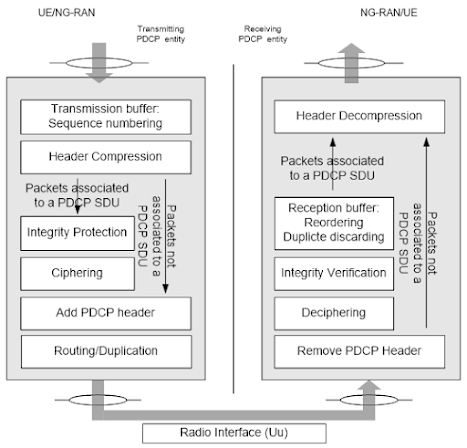
Source — 5G | sharetechnote.com
Functions of this layer are :
- Header Compression : As when control Information is add up with the data Packets such that IP address IPv4 or IPv6 , the size of data packets increase , so to reduce the size header compression is needed .
ROHC (Robust Header compression) which is an algorithm used to compress headers of various IP Packets.
- Ciphering and Integrity Protection : Ciphering is to encrypt the data so that third party cannot understand what is going and from and where it is going . This is used to prevent Eavesdropping.
Integrity protection is used to verify that the data originated from the right source .
- Routing and Duplication of Split-Bearers : As UE is connected to different gNB then we split and duplicate the data so as to maintain quality of services by sending some data to one gNB and some data to other one.
- In Sequence-Delivery : The data packets are provided with a sequence number so that PDU’s stored in Buffer until all previous PDU’s are received.
- RLC ( Radio Link Control ):
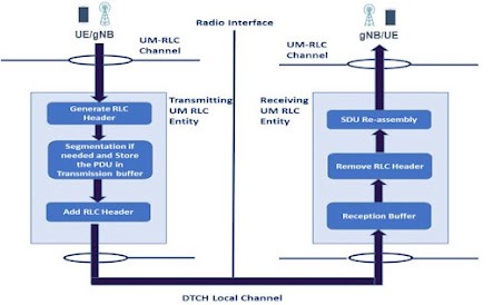
Source — techplayon.com
Functions of this layer are :
- Segmentation : Data is divided into segment so as to make data size that it can go through transport block.
- ARQ (Automatic Repeat Request)- Retransmission : This is used to retransmit the data packets when there is a negative acknowledge from the receiver’s end.
Three different RLCs Modes:
- Transparent mode : No Segmentation , No Duplicates Removal ,No Retransmission .
- UnAcknowledged mode : No Retransmission, but Segmentation.
- Acknowledged mode: Retransmission and Segmentation , Duplicated detection and removal.
- MAC ( Media Access Control ) :
Source — techplayon.com
As each layer provide and get services from above and below layers.
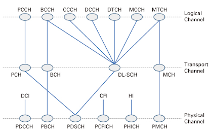
MAC layer provides services to RLC layer in form of Logical Channels and uses the services of Physical (PHY layer) in form of transport layer.
Logical Channels : These Channels are defined as what type of information they carries. Logical Channels can be one of the two groups
- Control Channels : These Channels are used to transmit and configure the data necessary for operating in our system.
- Traffic Channels : These channels are used to transfer user plane data.
Logical Channels in the above image are as follows:
- PCCH (Paging Control Channel )
- BCCH (Broadcast Control Channel)
- CCCH ( Common Control Channel)
- DCCH ( Dedicated Control Channel)
- DTCH ( Dedicated Traffic Control Channel)
Transport Channels in the above images are as follows:
- PCH (Paging Channel)
- BCH (Broadcast Channel)
- DL-SCH (Downlink Shared Channel)
- UL-SCH (Uplink Shared Channel)
Carrier Aggregation:
This terms is used in to increase data rate per user which directly increase the frequency blocks (component carriers) assigned to a user.
Functions of this layer are :
- HARQ ( Hybrid Automatic Repeat Request ): This is combination of High rate Forward Error correction (FEC) and ARQ retransmission on error data.
This function of MAC layer check for error messages in a pool of received messages and retransmits them through the scheme of ARQ on the sender side .
Until sender get Negative Acknowledgement(NAK) regarding the particular data , sender will retransmit it until it will not get NAK.
source- techplayon.com
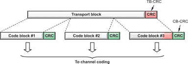
If there is large transport block then it divided into Code Block Groups(CBG) and if particular data is getting NAK then we transmits particular CBG instead of transmitting the whole transport block.
- Scheduling : This is used to allocate the resources depending upon the following three factors:
- Data Connections
- Data Priority
- Buffer Status
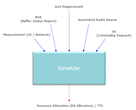
source — 5G | sharetechnote.com
If there are some users connected to the same gNB then how things are scheduled so that each one of them get data , so scheduler make decision according to the above three mentions categories , so it get by this which user will serve first and in a preemptive way and so on.
5.PHY ( Physical ) Layer :
Source -techplayon.com
As you can see in above image that Physical Layer getting its services from the Transport Channel(which is a part of MAC Layer) ,hence getting services from MAC.
So first take a look on the Physical channels:
- PDCCH ( Physical Downlink Control Channel ) :This channel is used for downlink control information like scheduling sessions.
- PBCH ( Physical Broadcast Channel ) : This channel have the system information which is used by UE for getting the MIB(Master Information Block).
- PDSCH ( Physical Downlink Shared Channel ) : This is the main Channel through which paging and data which is sending from the network to the UE(User Equipment) , such as system information.
- PUSCH ( Physical Uplink Shared Channel ) : This is the main channel for the devices to send uplink data to the network.
- PUCCH ( Physical Uplink Control Channel ) : This is the channel through which Hybrid ARQ Acknowledgement send from the device side to the network regarding the transport blocks which is send from the network to device side.
- PRACH (Physical Random Access Channel) : This channel is used for physical random access procedures.
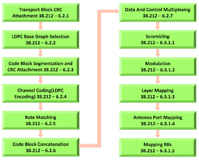
Functions of Physical Layer are as follows:
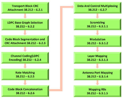
Source — resourcegate.net
- CRC ( Cycle Redundancy Checks ) : This checks is used for error detection as some redundant bits are add up to the data for checking at the receiver side as its get any error or not in transmissions. Its checks the transport blocks through the generator polynomial which is generated at the sender side, as redundant bits are calculated using this generator polynomial.
- LDPC ( Low Density Parity-Check ) : This check is used for error correction as error has already detects by the CRC .Its uses two parameters.
- Transport Block Size(TBS)
- Code Rate
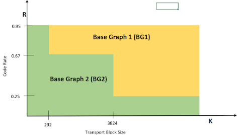
Now if TBS and Code Rate are above the threshold(Minimum) then Base Graph 1 will used for LDPC , otherwise Base Graph 2.
If Transport Block size is greater than it is breakdown into code blocks and each code block is go through LDPC coding .
So , this gives us a benefit of not retransmitting the message or data on found of error as LDPC correct it but in some cases when whole transport block get corrupted then there will be a case of retransmission of the data.
- Rate Matching : This is used for transmitted the extract set of bits from each code block in a given interval of time as all bits cannot be transmitted at the same transmitted time .
- Scrambling : This is used for as UE is hearing signals from many gNBs(RAN) , So Scrambling code block is multiplied by Scrambling Sequence and which device have this Scrambling Sequence can hear the signal corresponding to that gNB only and all other signal will be treated as interference to the UE.
- Modulation : This is for modulation of the scrambled bits from 1’s and 0’s to a complex modulated symbols. Each Symbols give ’n’ bits depending on the used modulation scheme. Some Modulation Scheme are QPSK, 16 QAM ,64 QAM , 256QAM .
- Layer Mapping : As in 5g NR , special multiplexing is used , so it is possible to transmitted multiple layer of data through multiple antenna terminology.
- Antenna Mapping : As different layers of data are there so we have to mapped virtual antenna ports . Pre-Coding matrix is used for mapping the different numbers of layers into the corresponding virtuals ports .
Now physical antenna are more than the virtuals antenna so linear mapping is done from virtual antenna ports to physical antenna ports .
- RRC-NAS (Radio Resource Control )-(Non-Access Stratum)
Functions of RRC (UE-gNB) :
- Broadcast of System Information
- Radio Bearer Establishment
- Connections Establishment and release Functions
- Paging
There are three types of RRC modes in NR :
- RRC-Idle
- RRC-Inactive
- RRC-Connected
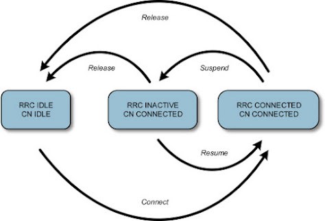
Source -ScienceDirect.com
when device is turned on for the first time so it is in RRC-Idle mode and when it is connected to the network it is in RRC-connected mode and communications happen between the device and the network.
Now RRC context is stored both in UE and gNB when there is no communication it has to go RRC- Idle mode again so to save battery . After that when it want to come again in RRC-Connected mode , it has to do a lot of Control-signaling. So there is a introduce of RRC-Inactive mode which stored the RRC context and UE can also go to sleep for energy saving . Thus this mode have resolved the issue of going again and again for Control-signaling and give benefits of both performance and energy efficient .
There is RRC-Suspend and RRC-Resume for suspend from connected mode to inactive mode and from inactive to connected mode respectively.
Functions Of NAS (UE-AMF) are as follows:
- Authentication and Security
- Idle Mode Enabling Paging
- Session and mobility management
AMF here is Access and Mobility Function which is a part of 5g core network . We will see its function in 5g Core networks series.