This image illustrates 5G network slicing and its end-to-end architecture:
Left Side – Radio Access Network (RAN) Slicing:
- Shows two User Equipments (UEs):
- UE1 with
SST=1, SD=1(Slice Service Type 1, Slice Differentiator 1) - UE2 with
SST=1, SD=2
- UE1 with
- The PHY layer is split into “Slice 1” and “Slice 2”, separated over time and frequency resources – each corresponding to a specific network slice.
- Upper RAN protocol layers (MAC, RLC, SDAP, PDCP, RRC) remain common but may enforce slice-specific behavior.
Right Side – 5G Core (5GC) Network Slicing:
- Different Network Functions (NFs) like SMF (Session Management Function) and UPF (User Plane Function) are highlighted in separate overlapping colored areas – indicating dedicated instances for each slice.
- The NRF (Network Repository Function) overlaps, indicating shared functionality across slices.
- Other shared control-plane NFs like AMF, AUSF, NSSF, UDM, and UDR remain common for all slices.
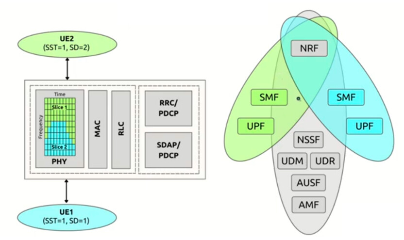
Each slice (defined by SST and SD) has dedicated resources in both the RAN and Core Network, enabling isolation, customization, and optimization for different services or tenants.
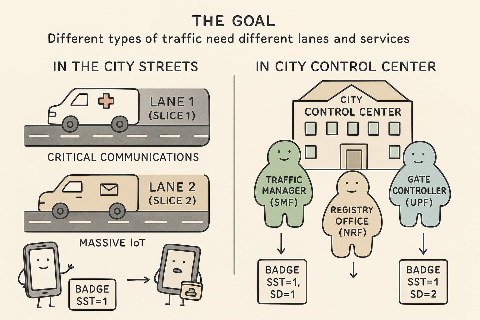
Analogy: A Smart City with Personalized Highways and Control Centers
 The Goal:
Different types of traffic (cars, ambulances, delivery vans) need different lanes and services – fast lanes, security checks, or delivery docks.
 In the City Streets – The RAN (Left Side of the Image):
- Imagine the RAN (Radio Access Network) like a city highway system.
- It has multiple lanes (slices) designed for different types of vehicles:
- Lane 1 (Slice 1) is for ambulances (critical communications)
- Lane 2 (Slice 2) is for delivery vans (e.g., massive IoT)
- Each vehicle (UE1, UE2) is assigned a lane depending on its job.
![]() These lanes are carefully separated in space and time, so there’s no traffic jam or interference.
These lanes are carefully separated in space and time, so there’s no traffic jam or interference.
 In the City Control Center – The 5G Core (Right Side of the Image):
- Think of the Core Network as the smart city’s control center with departments:
- Traffic Managers (SMFs)
- Gate Controllers (UPFs)
- Registry Office (NRF)
- Identity Desk (UDM, AUSF)
![]() Each lane (slice) has dedicated managers:
Each lane (slice) has dedicated managers:
- One set of SMF/UPF for ambulances,
- Another set for delivery vans,
- But they all share the same building and basic support staff (AMF, UDM, etc.).
 The Devices (UE1 and UE2):
- Each vehicle (UE) has a badge showing its assigned lane:
SST=1, SD=1= Ambulance sliceSST=1, SD=2= Delivery slice
When they enter the network, they are directed to their specific lane and their control center staff.