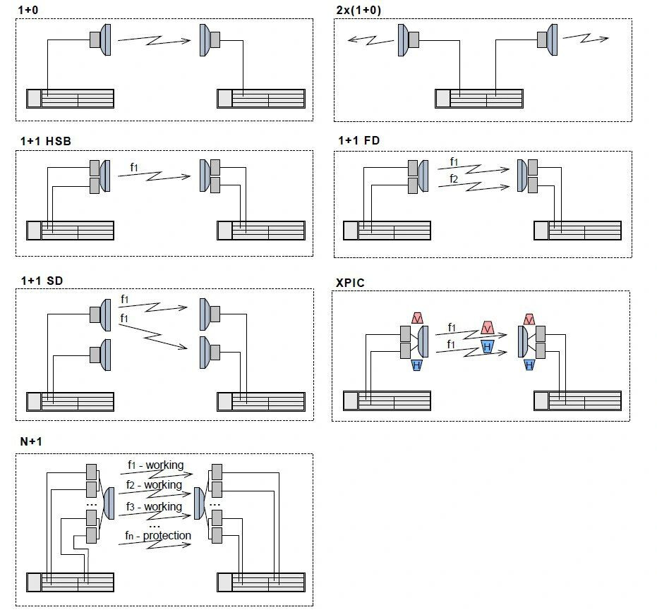
1+0
-
Definition: A single transceiver and antenna are used for transmission and reception without redundancy.
-
Use Case: Suitable for applications where no backup is required and cost is a constraint.
2x (1+0)
-
Definition: Two independent 1+0 links are used in parallel to provide higher capacity or for separate services.
-
Use Case: Used for capacity enhancement or segregation of traffic.
1+1 HSB (Hot Standby)
-
Definition: Two transceivers and antennas are configured on the same frequency (f1), with one acting as the active link and the other as a standby link. The standby link activates in case of failure.
-
Use Case: Provides redundancy with automatic switchover for critical systems.
1+1 FD (Frequency Diversity)
-
Definition: Two transceivers operate simultaneously on different frequencies (f1 and f2) for redundancy. If one frequency fails, the other continues operation.
-
Use Case: Used in areas with high interference or fading conditions.
1+1 SD (Space Diversity)
-
Definition: Two antennas at different physical locations (to mitigate multipath fading) transmit and receive on the same frequency (f1). Both antennas feed the same transceiver.
-
Use Case: Ideal for environments prone to fading caused by terrain or obstructions.
XPIC (Cross-Polarization Interference Cancellation)
-
Definition: Two transceivers operate on the same frequency (f1), but each uses a different polarization (horizontal or vertical). The interference is canceled out electronically.
-
Use Case: Maximizes capacity in a single frequency channel using polarization multiplexing.
N+1
-
Definition: N working transceivers operate on distinct frequencies (f1, f2, …, fn), with one additional transceiver serving as a protection unit. The protection unit takes over in case of any working transceiver failure.
-
Use Case: Commonly used in multi-channel links to ensure service continuity with minimal redundancy cost.
LinkedIn: ![]()