
A modern wireless network depends on multiple systems, meshing together, to provide the customer with a positive experience. Microwave communications, used for backhaul applications that move site traffic on and off of the core network, can make or break that positive customer experience.
Content.
- Environmental considerations.
- Mechanical and structural factors.
- Structural Considerations.
- Installation.
- Conventional antenna alignment (RSSI alignment).
- Alignment using spectrum analyzer.
- Cross polarization adjustment.
- Diversity antenna alignment.
- Influence of weather during antenna alignment.
- Installer fatigue and frustration.
Environmental considerations.
While operators demand near-perfect uptime (up to 99.999% availability), achieving this in adverse environments presents a significant challenge. Microwave links often reside in remote locations, areas where traditional wired connections are too expensive or impractical. This exposes them to the force of nature, including extreme weather conditions and other environmental factors. To ensure reliable communication, microwave systems must be specifically designed to withstand these demanding conditions.
Wind Loads.
Wind load is the primary mechanical stress on a microwave antenna installation. Due to their reliance on Line-of-Sight (LOS) propagation, microwave antennas are typically mounted high above ground in exposed locations, making them highly susceptible to wind forces. Their size and position further amplify wind effects, impacting not only the antenna’s structural integrity but also the supporting tower.
Variable Winds.
Direct force is not the only threat winds pose to microwave antennas. There also exists the phenomenon of wind-induced vibration, which can be problematic even in light breezes. Wind has a natural frequency of about 8 Hz. If an antenna or any equipment mounted to it has a similar natural frequency, then the wind can induce vibration. Over time, this vibration can compromise the mechanical integrity of the installation through structural fatigue, shortening the operational life of the antenna.
Corrosion Hazards.
In addition to wind, there are environmental chemical factors that can shorten the operational life of an exposed microwave antenna or its associated equipment. For instance, in coastal areas, airborne salt can cause corrosion. In developed urban areas, pollution from vehicle exhaust can have a similar effect. In industrial areas, there can be high concentrations of other corrosive chemicals vented by nearby factories, refineries or other sources. Often, more than one of these factors may be present.
Temperature and Humidity.
While temperature and humidity generally have very little effect on microwave operation, a challenge does exist in the installation of elliptical waveguide transmission line. To maintain efficient operation, the air inside the waveguide must be kept dry during installation and operation; otherwise, condensation can occur as temperatures drop. In addition, installing waveguide in extremely low temperatures makes it more likely that damage will occur to its outer jacket.
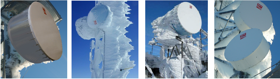
Ice buildup and radomes.
As the temperature drops, the risk of ice buildup rises. Open and exposed, microwave antennas are prone to ice, particularly in areas where humidity levels are high. While antennas and their mounts are designed to bear the weight of this ice, a problem emerges when the ice obstructs the antenna’s LOS path.
Solar radiation.
Ultraviolet (UV) radiation from the sun damages more than sunbathers’ backs. Over time, it also causes many plastics to become brittle and can even cause them to fail. Since microwave antennas are open and exposed to sunlight, any critical component made of non-UV-resistant plastic will experience this degradation. Reputable antenna manufacturers specify UV-resistant materials in their products and verify their performance through rigorous testing.
Mechanical and structural factors.
Operational wind load: The maximum wind speed at which an antenna will continue to maintain the majority of the beam energy on the antenna at the other end of the link.
Angular movement: The shifting or twisting of a microwave antenna as a result of environmental conditions, which can result in lower signal strength or even total link failure.
Survival wind load: The maximum wind speed a microwave antenna can experience without permanent damage.
Wind can cause a microwave antenna to physically sway, leading to misalignment and a phenomenon known as beam pointing error. Imagine a laser pointer, a slight tilt redirects the concentrated beam off-target. Similarly, wind-induced antenna movement disrupts the focused microwave signal, causing it to miss the receiving antenna.
The acceptable beam pointing error is typically defined as 0.3 times the antenna’s 3 dB beamwidth.
3 dB beamwidth refers to the angle within which the microwave signal retains most of its power (strength).
Larger antennas or those operating at higher frequencies have narrower beamwidths (more focused signals) and thus, lower tolerances for wind-induced movement.
The survival wind load represents the maximum wind speed an antenna can endure before experiencing mechanical failure. At these extreme wind speeds, the antenna might start to slip around the pole and some realignment may be required to restore the link to full operation.
The addition of side struts can provide greater stability at wind speeds up to the survival rating, but this should be verified and recommended by the antenna supplier.
Structural Considerations.
As with any structure, the best results proceed from solid foundations. In the case of a microwave antenna, that foundation is the tower or mounting pole that supports it. These, too, must be tested and rated to withstand wind loads and minimize twist and sway.
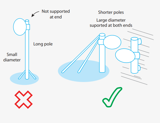
For example, a 60 cm (2 ft) microwave antenna mounted to a long, thin-walled, small-diameter pipe attached at only one end would create enough movement to lose antenna alignment, even without the addition of wind. While this may be barely adequate for, say, a low-frequency antenna with large beamwidth, it would certainly result in total link failure for an antenna of higher frequency.
Cantilever (one support end) pole installation introduces sway, and is not recommended.
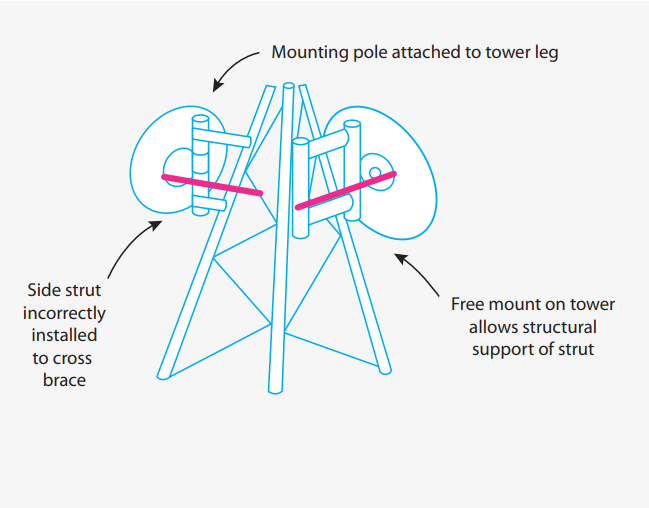
Tower mounting pole must be attached to the tower leg, not a cross brace.
Best practices for a solid structural foundation:
- Use large-diameter pipe up to 120 mm (4.7 in) for greater rigidity.
- Shortest possible pole lengths to improve antenna access.
- Rigid supports at both ends of the mounting pole, attached to tower leg, wall or similar.
- Don’t attach poles to tower cross braces. Ensure interface steelwork design doesn’t put excess stress on the tower structure.
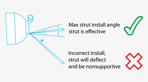
Struts: A stiffening arm installed with a large antenna to improve its stability, accuracy and wind survivability.
In larger installations, the antenna will require the installation of one or more side struts. Poorly or improperly installed struts may allow antennas to move under wind load and shorten their operational life through mechanical fatigue.
Struts installation guidelines:
The angle at which the strut is installed should be within guidelines specified by the manufacturer. Failure to do so can result in flexing or bending of the strut. Ideally, the strut will be most effective if mounted perpendicular to the antenna.
The side strut should be attached to an approved structural support designed to have such an attachment made. Cross braces do not meet this requirement ,tower face mounts are a better solution.
Installation.
The installation and commissioning of the microwave link is a critical stage in the overall system process.
No matter how well the link has been planned, or how much care has been taken in the selection of equipment, poor installation practices will jeopardize the link’s reliability and deliver performance far below planned expectations. Further complicating things, every installation is different. The location of the site, the direction of the antenna, the presence of nearby equipment, and other prevailing local conditions mean each installation presents unique challenges requiring careful attention. There are no one-size-fits-all solutions or processes for this challenge. While manufacturers provide detailed instructions on how to best assemble and install equipment, it’s the expertise, skill and care of the installation crew that will ultimately determine if the link fulfills its performance and reliability goals.
Installation can be challenging, requiring consideration of several factors to ensure that:
-
Available space exists on the structure at the specified height.
-
The antenna will be able to be oriented to a rough compass heading.
-
The antenna will be able to move freely from side to side during alignment.
-
The correct offset is used in the installation of the antenna mount.
-
There is a clear transmission line path to the antenna feed.
-
There is a suitable location for strut collars.
-
Strut collars are mounted within manufacturer-specified tolerances.
-
Strut ends can move freely past the collar during the alignment process, without coming into contact with other objects.
All supporting steelwork should be mounted on the tower. Pipe mounts should be vertically leveled (unless specifically required to meet a different orientation) because unleveled mounts have a significant effect on the alignment process.
Conventional antenna alignment (RSSI alignment).
One of the most important stages of installing a microwave point-to-point link is proper alignment of the antenna system. Any misalignment can cause unstable operation and will decrease the fade margin that will affect the overall link reliability. While usually straight-forward, alignment on some links can become time consuming and frustrating if done incorrectly.
Depending on the size and frequency of the antenna being installed, the target antenna on the other end of the link may be anywhere from a few hundred meters to several tens of kilometers away. Although all links require a clear LOS path between end points, it’s not always feasible to visually orient an antenna to a distant point.
Microwave antennas must be accurately positioned on true azimuth, that is, absolutely horizontal and level, before path alignment. Most alignment difficulties are the result of incorrect azimuth position or inadequate leveling.
Signal strength readings are usually measurable when at least the main beam of one antenna and its first side lobe of the other antenna are aligned. The strongest signal occurs at the center of both main beams.
Before starting the antenna alignment:
- Know your target received signal level (and according radio RSSI voltage) from link budget calculation. Typically, the target received signal level in the field is within +/- 3dB of the calculated value.
- Know the azimuth and elevation angles for alignment.
- Ensure radios are fully configured and tested on the bench before taking them into the field.
- Disabling ACM (Automatic Channel Modulation) and ATPC (Automatic Transmit Power Control): By disabling these features initially, the radios will not automatically adjust modulation and transmit power based on the link conditions. This allows for manual configuration of these parameters according to the precalculated link budget.
- Configuring Radios in Accordance with Link Budget: Based on the link budget analysis, the radios are configured with specific parameters such as transmit power, modulation scheme, and bandwidth. These parameters are selected to ensure that the received signal level at the receiver (Rx level) meets the required threshold for reliable communication.
- Enabling ACM and ATPC After Successful Precalculated Rx Level Achievement: Once the radios are configured and the precalculated Rx level is achieved, ACM and ATPC can be enabled. ACM allows the radios to adapt modulation and bandwidth dynamically based on the current link conditions, optimizing performance. ATPC adjusts the transmit power to maintain the desired received signal level, compensating for changes in link quality.
- Fallback Procedure for Alignment Issues: In cases where alignment issues arise, such as when the link distance is longer than anticipated, a fallback procedure is suggested. This involves aligning the antennas using minimum modulation, minimum bandwidth, and maximum transmit power settings. These settings help maximize the signal strength transmitted from one antenna to the other, aiding in alignment and link establishment.
- Agree on antenna polarization. It can be frustrating to attempt aligning the antenna only to discover that the other team is using a different polarization. If Rx levels remain stubbornly low, double check polarizations on both ends. Radios installed with incorrect polarizations may have a signal loss of 20 - 30dB or greater.
Alignment should be seen as two stage process: coarse alignment and fine alignment.
Coarse alignment.
Vertical: It is recommended to begin with vertical alignment. Using a level tool, set both antennas to null position vertically. This will ensure a better starting point for long links with limited eye visibility typically requiring large diameter antennas with narrow beamwidths.
Horizontal: Position the antenna horizontally using a compass or GPS (note the difference between true and magnetic azimuth). Azimuth angles should be known from link planning report. When using a compass, be aware that large metal structures such as towers may distort compass readings.
Fine alignment.
Before:
- Get a good quality voltmeter that you will connect to the radio.
- Have a team at each end to make the alignment process easier and faster.
- Remember to adjust only one side of the link at a time.
- Remember that point-to-point systems must have a clear radio line-of-sight. Even if the remote site has clear eye visibility, radio line-of-sight is defined by 60% of the first Fresnel Zone. The Fresnel zone for a radio beam is an elliptical area immediately surrounding the visual path. It varies in width depending on the length of the signal path and the frequency of the signal. If an object, such as a mountain ridge or building, is too close to the signal path, it can reduce strength of the radio signal and desired Rx level will not be achieved. This happens even though the obstacle does not obscure the direct, visual line-of-sight. The necessary clearance for the Fresnel zone can be calculated, and it must be taken into account when designing a link.
- Remember that the key characteristic of any antenna is its radiation pattern. It describes how the antenna will transmit the signal. Looking at the radiation pattern, it’s clear that the signal propagates in multiple paths (directions). These paths are called lobes. Each antenna has a main lobe and several side lobes. The difference in amplification (signal strength) between the main lobe and side lobes is typically around 20 dB. This, of course, varies with antenna size,frequency, and class. Small antennas in low frequency range typically have strong side lobes, which sometimes results in installation crews aligning the antenna on a side lobe instead of the main lobe. When an antenna sweep is performed and an initial signal is found, installers typically stick with this first signal and do not continue the antenna sweep. If this initial signal happens to be a side lobe, the antenna will most likely be aligned to it, resulting in poor link performance.
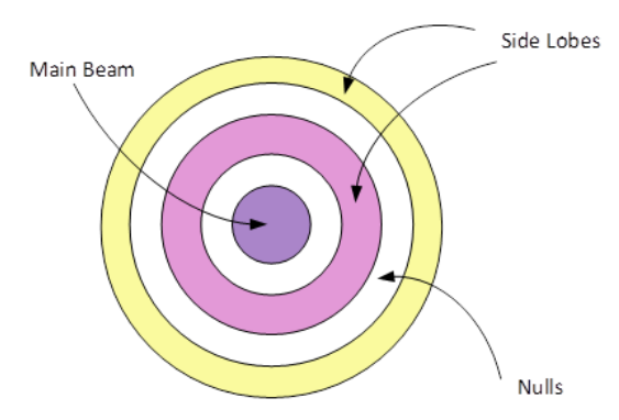
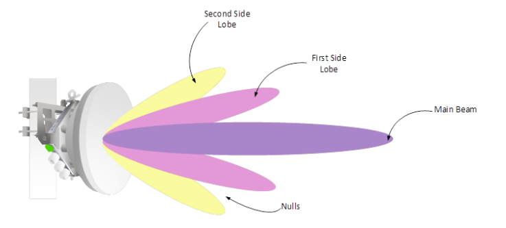
Main Beam – the center of the radiated signal; has the highest power level. Side Lobes – areas of increased signal strength; weaker than the main beam. Nulls – areas between the side lobes; little or no signal.
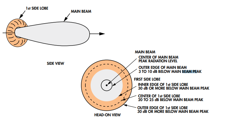
First lobe false positives: While aligning a microwave link, it’s easy to mistake the first lobe signal strength for the main beam strength.
Because of the shape of the signal, the strongest part of the first lobe is actually stronger than the edges of the main beam.
Step by step actions:
- Perform full vertical sweep by moving the antenna up and down (vertically). Start by moving the antenna from the upper side to avoid alignment to a signal reflected from the ground. Look at the voltmeter and try to catch the moment where the received signal is the best.
- After you have found the point where the signal is the highest vertically, perform full horizontal sweep by moving the antenna right and left (horizontally). Find the point where the signal is the best horizontally.
- The point that has the highest received signal level horizontally will be the point where the received signal level is the strongest on the antenna.
- When the highest signal level is obtained during the alignment of the first antenna, fix it and repeat the same steps with the second antenna.
- After finding the highest signal level on the second antenna, repeat alignment steps again on the first antenna until the maximum calculated signal level (+/- 3dBm) is reached.
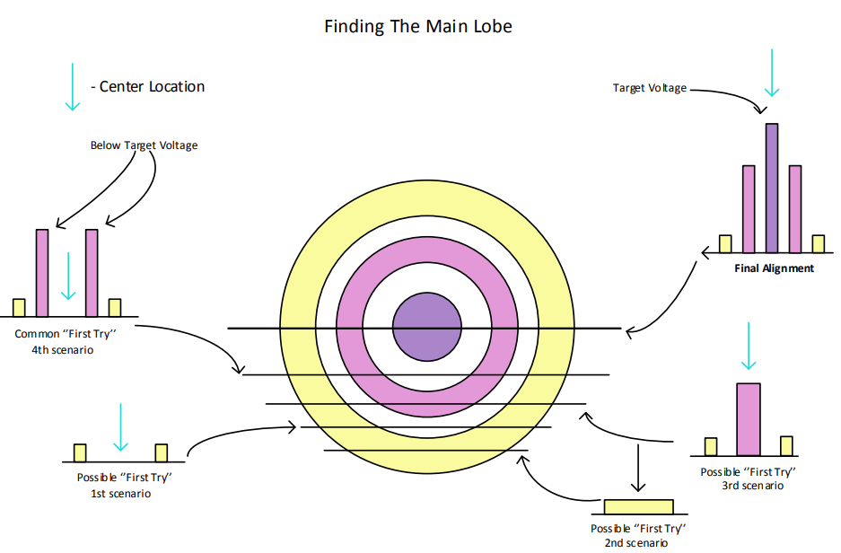
- When finding the signal peaks, which are suspected to be side lobes, analyze the signal peaks found.
- In case of two approximately equal signal peaks, it is most likely that a side lobe has been found in the current adjustable plane. Aligning precisely on one of those peaks may result in an improper overall alignment result. 4th and 1st scenario. In case of a single prominent signal peak, it is most likely that an approximate center position is found. 2nd and 3rd scenario.
- During short link alignment over urban areas, try to avoid alignment to reflected signal from reflective planes such as rooftops or lakes in the middle of the path. In order to avoid it, always start Vertical plane sweep from the top, meaning antenna should be aligned “into the sky” before you begin.
Antennas sized up to 1.2m have a wider main beam and more evident side lobes.
Typical error: antenna is aligned on the side lobes.
Bigger antennas with a higher gain have a narrow main beam and less relevant side lobes.
Typical problem for installators: finding the first signal from the far side site.
Alignment using spectrum analyzer.
Every missed dB will increase annual link downtime and decrease its availability, which can be a drawback for potential customers, whether you are a service provider, mobile operator, or an installation and maintenance company.
In general, there are two potential issues when aligning antennas. First, when aligning small antennas, it is difficult to avoid the side lobes. Second, with larger antennas (6ft/1.8m and more), the difficulty lies in finding the initial signal.
A spectrum analyzer is an instrument used to measure the strength (magnitude) of a signal across different frequencies. Unlike a radio interface that might only display the total received signal level (e.g., -50dBm), a spectrum analyzer shows a more detailed picture. It creates a graph (called a spectrum) that reveals how the signal’s power is distributed across a range of frequencies. An example is given below.
Performing the initial antenna sweep with a voltmeter or by using the radio’s built-in indicators will only give you a number value (e.g., voltage or RSSI) representing the total signal strength. They don’t reveal the specific signal being targeted or potential interference present
Benefits of using a Spectrum Analyzer include:
- Superior Sensitivity: Spectrum analyzers can detect weaker signals compared to most radios, making initial signal identification faster.
- Faster Sweeps: Their rapid sweep speeds allow for quicker antenna adjustments during alignment.
- Accuracy and Documentation: Spectrum analyzers provide precise measurements and a visual representation of the signal, serving as documented proof for troubleshooting purposes.
- Improved Resolution: They offer a more detailed view of the signal, enabling differentiation between the desired signal and unwanted noise or interference. This allows for more accurate antenna alignment.
- Visual Analysis: The graphical display of the spectrum allows for identifying potential issues like signal reflections, interference, or damaged equipment.
- Direct dBm Measurement: Spectrum analyzers measure signal strength directly in dBm, eliminating the need for voltage-to-dBm conversions.
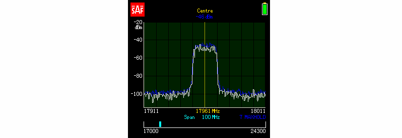
Nearly every spectrum analyzer, comes with multiple possible trace modes. The displayed data will depend on the chosen trace mode. For example, “max hold” trace mode will add another spectrum curve on the screen, displaying the maximum achieved signal strength in this trace mode. This is very helpful in antenna alignment, as you no longer need to memorize the highest achieved signal levels, with them being displayed on the screen after a full antenna sweep. In order to align the antenna on the main lobe, you just have to turn it back until the real-time reading matches the previously registered “max hold” curve. In addition to that, you will also be able to verify that there is no interference and that the antenna is not aligned on a reflected signal.
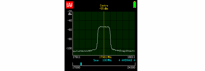
Let me give you an example of a spectrum curve of a properly aligned antenna, along with a “max hold” trace on the screen.
From the picture, you can see that:
- The real-time reading (white line) matches the “max hold” curve (blue line).
- Top of the signal is even without any notches or spikes. This means that there are no reflections, hardware failures, or unexpected fading.
- Adjacent channels do not have any signals, so the spectrum is clear and the installed link should not suffer from any interference issues.
In order to determine the absolute power of the signal, it is necessary to use the “power in band” function. In other spectrum analyzers, the function might also be called “channel power measurement”. This is a mathematical function that sums all the separate spectrum energy points and provides the absolute power level of the signal. In other words, the absolute power level is the number that shows up in the radio management graphical interface and is provided in link budget calculations.

Here is another example, showing how a spectrum analyzer can help to identify issues with radio signal propagation. We can see that the “power in band” value matches the link budget calculation, indicating sufficient overall signal strength. However, the spectrum analyzer’s visual representation of the signal reveals a “damaged” curve, suggesting potential issues with signal quality despite adequate power.
Potential Problems: This damaged curve could indicate factors like:
- Multipath interference: The signal might be arriving over multiple paths, causing distortions.
- Signal reflections: Reflections from nearby objects could be affecting the signal shape.
Impact on Performance: These issues, though not affecting the raw power level, can degrade the signal-to-noise ratio (SNR). A poor SNR translates to reduced data transmission quality and potential communication errors.
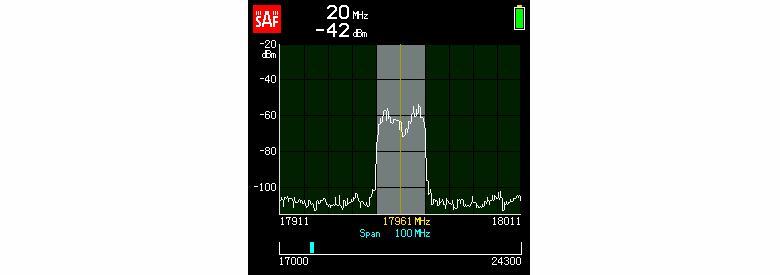
Voltmeter Limitations: A simple voltmeter wouldn’t detect these quality issues, potentially leading to an undetected problem during installation and requiring a return visit for troubleshooting.
Cross polarization adjustment.
Cross-polar discrimination (XPD): The ability of an antenna to distinguish between signals of differing polarization. (e.g., horizontal vs. vertical).
XPD in Transmission and Reception:
- Transmit XPD: This refers to the amount of unwanted signal leakage into the orthogonal polarization during transmission. Ideally, an antenna transmits only in the intended polarization.
- Receive XPD: This signifies the antenna’s capability to maintain the purity of the received signal’s polarization, minimizing unwanted components from the orthogonal polarization.
Impact of Imperfections:
Even in a perfectly designed system, electrical and mechanical imperfections within the antenna can introduce slight distortions, causing a small amount of ellipticity in the received signal’s polarization. This means the signal starts to exhibit characteristics of both its intended polarization (e.g., vertical) and the orthogonal one (e.g., horizontal). The XPD value quantifies the ratio of this unwanted horizontal component to the desired vertical component.
Importance of XPD:
XPD is particularly crucial in dual-polarized systems. These systems utilize both horizontal and vertical polarizations to potentially double the channel capacity. However, poor XPD can lead to cross-talk between the polarizations, where signals in one polarization interfere with those in the other. This can significantly degrade system performance.
Mitigating Cross-Talk:
- XPICs (Cross-Polarization Interference Cancellers): Radios can employ XPICs to isolate the desired polarization and compensate for some level of cross-talk induced by the link or propagation conditions.
- Importance of Good Antenna XPD: However, for XPICs to function effectively, the antenna itself needs to have good XPD. This provides a cleaner signal with minimal unwanted components, allowing the XPICs more flexibility in mitigating the remaining cross-talk.
Consequences of Low XPD:
- Degraded Network Performance: Poor XPD can translate to slower data transfer speeds, inefficient use of the allocated spectrum, and ultimately, dissatisfied users.
XPD and Alignment:
- Cross-polarization adjustment, a process of optimizing antenna positioning, is typically performed after completing the initial path alignment.
- Target XPD Value: Ideally, the difference in signal strength between the intended and unwanted polarizations (measured during adjustment) should be within a specific range (e.g., 3 dB).
XPIC Operating Range:
- XPI (Cross-Polarization Isolation): When XPICs are enabled, the XPI value, which is closely related to XPD, should be maintained within a certain range (e.g., 25 dB to 30 dBm) for optimal performance.
Diversity antenna alignment.
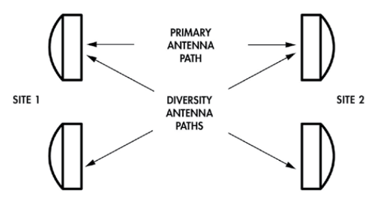
Long distance Microwave Links often use Space Diversity to ensure reliable communications between the two end points.
In certain geographic locations, such as over water and in deserts, multipath propagation poses an impediment to long-haul radio performance in the form of intolerable link outages. To compensate, a protection scheme must be applied. Space Diversity is one such widely implemented protection scheme that improves the performance of long-distance microwave radio links.
Spatial diversity employs multiple antennas, usually with the same characteristics, that are physically separated from one another. Depending upon the expected incidence of the incoming signal, sometimes a space on the order of a wavelength is sufficient. Other times much larger distances are needed.
Due to their separation, the multipath signals will arrive at the different antennas at slightly different times and with varying strengths.
By using a diversity combiner, the system selects the signal with the strongest strength or the least amount of distortion, effectively mitigating the impact of multipath fading.
Space Diversity is usually achieved using two vertically spaced antennas (space diversity), multiple transmitter frequencies (frequency diversity), both space and frequency diversity (quad diversity), or reception using two different antenna patterns (angle diversity). Frequency diversity was the first diversity used by fixed point to point microwave systems. Combining dual‐channel space and frequency diversity produces a powerful diversity improvement receiver configuration. The purpose of angle diversity antennas is to mitigate the destructive effects of multipath propagation without using a vertically spaced diversity antenna on the microwave tower.
Alignment of diversity antenna is performed after path alignment and cross polarization adjustment is complete. Diversity antennas are aligned with opposite site primary antenna. Perform path alignment and cross polarization adjustment on diversity antennas the same way as primary antennas. However, Do not move the primary antenna or primary feed. Adjust only the diversity antenna and diversity feed.
Influence of weather during antenna alignment.
Favorable weather conditions are crucial for accurate antenna alignment, especially in regions prone to inversions and fluctuating atmospheric conditions (varying k-factor).
Inversions: Atmospheric layers where temperature increases with altitude, affecting radio wave propagation.
K-Factor: A measure of how much the atmosphere bends radio waves, influenced by inversions.
Unstable Weather Distorts Signals: Phenomena like inversions and weather fronts can bend and distort microwave signals, making it difficult to achieve a precise alignment during these times.
Varying K-factor due to inversions makes microwave signal behavior less predictable and antenna alignment more challenging.
Ideal Conditions for Alignment: For optimal alignment, strive for periods with stable weather patterns. Generally:
Wind and Sun: These conditions often indicate stable air, making them favorable for alignment.
Cold Fronts: Once a cold front passes, the atmosphere tends to stabilize, offering a good window for alignment.
Warm and Stationary Fronts: Avoid aligning antennas during these periods as they are associated with more turbulent atmospheric conditions.
By waiting for periods of stable weather, you can ensure a more accurate and reliable antenna alignment, minimizing signal degradation later.
Additional Challenges: Reflective Surfaces
Planning the antenna placement beforehand is critical when aiming the signal across reflective surfaces like large bodies of water, dense urban environments with tall buildings, or narrow canyons. These surfaces can reflect the microwave signal, creating unpredictable signal paths and potentially hindering alignment.
A well-designed system that considers these reflective surfaces beforehand can achieve predictable and reliable signal transmission.
Installer fatigue and frustration.
When proper alignment becomes difficult to achieve, and all other possibilities have been eliminated, it’s time to consider the installer. It can be physically and mentally grueling to spend hours on a tower performing the same procedure over and over, and not improving the situation.
The pressure to complete the installation can sometimes lead some to accept a lower Received Signal Level (RSL) instead of achieving optimal alignment. This compromises the signal quality and potentially affects communication reliability.
Sometimes, a break or a fresh perspective from another technician can be the key to successful alignment.
Open communication between technicians and their support team when facing alignment issues. Discussing challenges and potential solutions can help them overcome obstacles and achieve optimal results.
Bibliography.
Microwave_Antenna_Selection_Guide: https://www.anixter.com/content/dam/Suppliers/RFS/literature/RFS-Microwave-antennas-selection-guide_ed2_2013-08-30.pdf
A robust protocol to compute wind load coefficients of telecommunication towers and antennas using numerical simulation for risk and resilience assessment: A robust protocol to compute wind load coefficients of telecommunication towers and antennas using numerical simulation for risk and resilience assessment - ScienceDirect
High_Wind_High_Ice_Series_7087: https://www.anixter.com/content/dam/Suppliers/RFS/literature/High_Wind_High_Ice_Series_7087_revA.pdf
Path alignment and cross polarization procedure for parabolic microwave antennas:
Antenna Alignment White Paper: https://www.saftehnika.com/files/downloads/611d60e5-6676-e211-bc32-0050569aa6cf/Antenna_alignment_White_Paper_SAF_Aug_2017.pdf
Antenna alignment using spectrum analyzer (part 2 of 3):
https://blog.saftehnika.com/en/whitepapers/point-to-point-antenna-alignment-using-spectrum-analyzer/
Back to Basics in Microwave Systems: Cross-Polar Discrimination: 2014 | CommScope
PTP 820-C, PTP 850-C XPI Alignment: PTP 820-C, PTP 850-C XPI Alignment - PTP - Cambium Community