A modern wireless network depends on multiple systems, meshing together, to provide the customer with a positive experience. Microwave communications, used for backhaul applications that move site traffic on and off of the core network, can make or break that positive customer experience.
Propagation and Path Loss.
Attenuation: The gradual loss of intensity (amplitude) in propagating waves, such as electromagnetic or sound waves, as they travel through a medium. This decrease is caused by various factors like absorption, scattering, and dispersion, which disrupt the energy transfer within the medium. Attenuation is typically measured in decibels (dB).
As the signal propagates, even a tightly directional LOS link’s beam experiences losses in transmission, known as path loss. This is due to several factors, including:
Free space path loss (FSPL) measures the reduction in signal strength solely due to the wave spreading out in all directions as it travels through free space (usually air), without considering obstacles, antenna characteristics, or equipment losses. Often expressed in dB for convenience, FSPL increases with both the distance travelled and the frequency of the signal (shorter wavelengths spread out more readily).
While FSPL is a valuable starting point, real-world links also experience additional losses due to factors like atmospheric absorption and terrain irregularities. These are addressed in the Friis transmission equation, which combines FSPL with antenna gains and other factors to calculate the total received power in a link.
Atmospheric absorption:
As microwave signals travel through the air, they are weakened by atmospheric absorption. Oxygen and water vapor molecules act like tiny sponges, absorbing some of the signal energy and converting it into heat. This effect is more noticeable at longer distances and specific frequencies. Other gases like nitrogen and carbon dioxide also contribute, though to a lesser extent.
It’s important to note that the absorption characteristics of the atmosphere are not constant. Temperature, humidity, and barometric pressure can all affect how much signal is lost. To combat these variations, techniques like frequency diversity are employed, spreading the signal across multiple frequencies less affected by absorption, ensuring reliable communication even under changing atmospheric conditions.
Diffraction:
In microwave communication systems, radio waves don’t simply travel in straight lines between transmitter and receiver antennas. They can diffract, or bend around obstacles, leading to signal reflections, cancellations, and path loss.
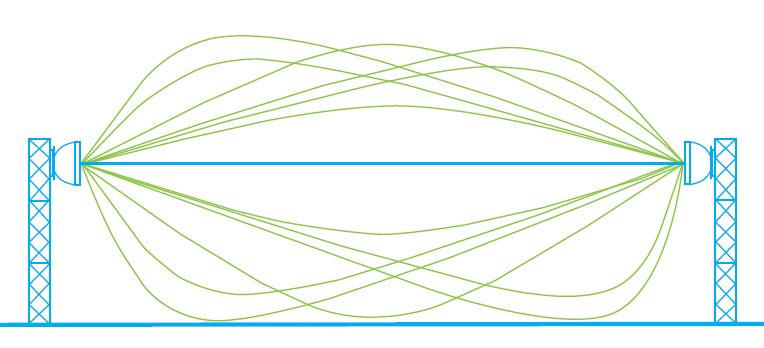
When microwave signals encounter obstacles like hills, buildings, or vegetation, they diffract around them. This diffraction creates multiple paths for the signal to travel, resulting in:
- Destructive interference: Rays arriving out of phase with the direct path cancel each other, weakening the signal.
- Constructive interference: Rays in phase with the direct path add up, enhancing the signal.
The strength of these interference effects depends on the difference in path lengths. In the near field (close to the antennas), these differences are highly variable, leading to complex signal variations. However, in the far field (beyond a certain distance), the dominant signal propagation occurs through a well-defined region called the first Fresnel zone (F1).
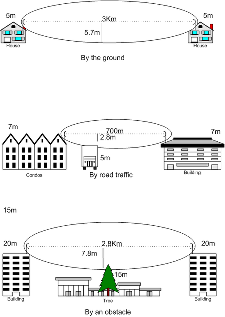
First Fresnel Zone (F1):
The F1 is an ellipsoid-shaped region centered on the direct path between the transmitter and receiver antennas. It contains 63% of the signal power in the far field. Clearing obstacles within the F1 is essential for minimizing diffraction loss and maintaining a strong signal. The ideal clearance, known as the first Fresnel clearance (0.6 F1), is often used as a design guideline to ensure reliable communication.
Factors Affecting Signal Strength:
- Frequency: Higher frequencies experience more diffraction, making F1 clearance more critical.
- Terrain: Hills, buildings, and other obstacles within the F1 can cause significant diffraction loss.
- Polarization: Horizontal and vertical polarization can have different diffraction characteristics.
- Atmospheric conditions: Temperature, humidity, and pressure can slightly affect diffraction.
Let’s see several examples of how Fresnel zones can be disrupted.
Path Loss:
The combined effect of factors like diffraction, distance, and atmospheric absorption is path loss, which weakens the signal as it travels between antennas.
Mitigation Techniques:
- Fresnel zone clearance: Minimizing obstructions within the F1 reduces diffraction loss.
- Higher antenna placement: Elevating antennas can help clear obstacles.
- Multiple paths: Using diversity techniques or relay stations can provide alternative paths to overcome obstacles.
- Power adjustments: Increasing transmission power can compensate for some path loss, but within regulatory limits.
Path reliability: also known as path availability, is the likelihood of a microwave link successfully transmitting data. It’s crucial for ensuring consistent communication and depends on various factors:
Path loss factors: This includes FSPL, atmospheric absorption, diffraction, and terrain irregularities. Flat terrain can lead to multipath fading due to signal reflections, while hot climates and frequent rainfalls increase attenuation.
Frequency: Higher frequencies offer greater capacity but are more susceptible to attenuation, especially rain. For frequencies above 10 GHz, even moderate rain can significantly impact signal strength.
Other factors: Multipath fading caused by reflected or refracted signals, interference from other sources, equipment failures, and atmospheric turbulence can also affect reliability.
Bit error rate (BER) is a crucial metric for measuring path reliability in digital systems like microwave links. It represents the percentage of transmitted bits that are received incorrectly, indicating errors in the communication channel.
1 error per million bits (1x10^-6) is sometimes used as a reference point for acceptable performance, but the precise tolerance depends on various factors and should be considered within the context of the specific system, application, and service requirements.
However, it’s important to remember that BER isn’t solely dictated by path reliability. Noise from other sources, modulation techniques, and receiver sensitivity also play a role. Additionally, while low BER is desirable, achieving perfect accuracy (BER of 0) is often impractical.
To combat errors, advanced systems employ error correction codes that can detect and sometimes even correct errors introduced during transmission. This allows for reliable communication even with slightly higher BER values.
Ultimately, the acceptable BER level depends on the specific application. Mission-critical systems, for example, might require BER values much lower than 1x10^-6 to ensure data integrity, while less critical applications might tolerate slightly higher error rates.
99.999% availability, often referred to as “five nines”, translates to just five minutes of downtime per year.
It’s important to note that achieving “five nines” or any other desired level of availability requires careful planning and design. Models like Vigants/Barnett-Vigants and ITU-R P.530 play a key role in this process:
- Vigants/Barnett-Vigants: This model focuses primarily on predicting path loss due to atmospheric effects like rain and fog, making it useful for designing microwave links.
- ITU-R P.530: This model is more comprehensive, considering not only atmospheric factors but also terrain irregularities, antenna characteristics, and other elements that can impact signal propagation.
The fundamental components.
The basic building blocks of a microwave communication system are shown next. They include a microwave radio transmitter connected to a directional antenna via a transmission line. The directional antenna’s outbound signal is aligned to a distant receiving antenna, which is connected to a radio receiver.
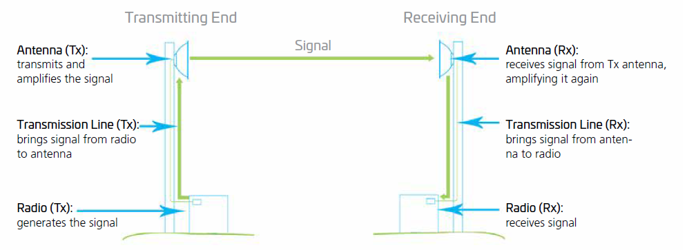
The radio:
Each end of the link has its own radio unit, typically with both transmission (TX) and receiving (RX) capabilities. (*)
(*): While both TX and RX capabilities are common, some microwave radio units might be dedicated solely to either transmission or reception depending on the network design.
They typically operate within specific frequency bands and have a power output of around 1 watt or less. Their throughput can range from hundreds of Mbps to several gigabits per second, depending on factors like bandwidth, modulation schemes (e.g., QPSK, 2048 QAM), and multiplexing techniques (e.g., FDM, TDM).
Higher-order modulation schemes offer increased throughput but can be more susceptible to interference. Adaptive modulation helps achieve a balance between throughput and reliability by adjusting the scheme dynamically based on environmental conditions.
Transmission lines:
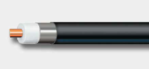
These are the physical media connecting the radio and directional antenna, and may be coaxial cable or waveguide. Because of the amount of signal loss they can introduce, the choice of transmission line type is determined largely by the frequencies in use.
Coaxial cables is suitable in applications using frequencies up to, or just above 2 GHz. (*) However, they experience higher signal loss at higher frequencies.
(*): High-quality cables can extend the usable range further.
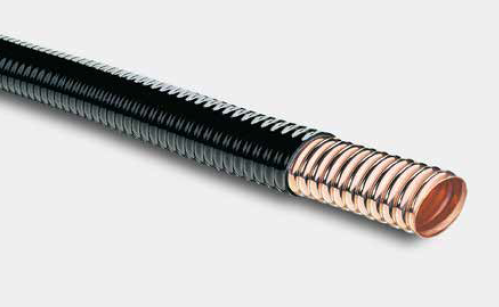
Elliptical waveguides, with their elliptical cross-section, are used in applications beyond 2 GHz thanks to their lower losses compared to coaxial cables. They typically operate in the dominant mode, supporting frequencies up to around 18 GHz. However, by using higher-order modes, they can extend their range beyond 40 GHz, though with increased complexity and potential downsides. While rarely used above 13 GHz in everyday applications, elliptical waveguides remain valuable for specific high-frequency needs.
Rectangular waveguides offer an even wider frequency range and better mode control compared to elliptical waveguides. However, their larger size and more complex design make them less common in general applications. Circular waveguides find use in specific high-frequency scenarios due to their unique properties.
Frequently, a split-mount radio with an ODU is mounted directly to the antenna with a special interface plate eliminating the need for transmission line all together.
The choice of transmission line depends on factors like frequency, distance, desired signal quality, and cost.
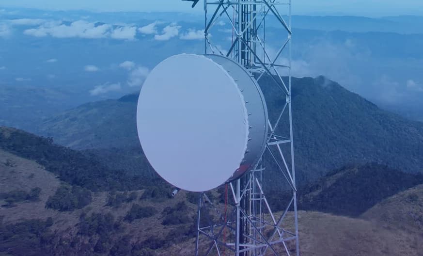
The antenna:
Microwave antennas, typically parabolic in shape for focused signal transmission, are polarized, either vertically or horizontally, aligning the electric field component of the wave for efficient propagation and potential interference reduction. The antenna size (dish diameter) is key: larger dishes offer higher gain, translating to stronger received signals over longer distances, but come with installation challenges and increased costs due to tower limitations.
While even high-quality parabolic antennas have some spillover (signal loss to the sides and back), advanced designs minimize this through precise shaping and feed horn construction, reducing interference and improving overall performance. Additionally, factors like antenna pointing accuracy and alignment are crucial for efficient signal transmission and reception.
Beyond parabolic antennas, horn antennas offer wider beamwidths for covering larger areas, while offset-feed antennas reduce blockage and improve pointing accuracy. Choosing the right antenna type and size depends on various factors like frequency, network design, distance requirements, and regulatory limitations.
Antenna properties:
The most important properties possessed by many antennas are polarization, radiation pattern. Directivity and power gain, radiation resistance, band width, effective aperture, power transfer and reciprocity.
I suggest exploring the article Microwave Antenna Performance Metrics for additional insights and information.
RF Filters:
These are specialized circuits that selectively allow or block specific radio frequencies.
In microwave systems, bandpass filters are commonly used to pass the desired signal frequency band while attenuating unwanted noise and interference from outside that band. This ensures cleaner signals and improved link performance.
Additionally, harmonic filters can be used to suppress unwanted harmonics generated by non-linear components in the system, further reducing interference and improving signal quality.
Control Units:
These are the brains of the network, responsible for monitoring, managing, and controlling various components.
They gather data on parameters like signal strength, power levels, antenna alignment, and environmental conditions.
Based on this data, they can adjust settings like modulation schemes, filter configurations, and antenna pointing angles to optimize link performance and ensure reliable communication.
Advanced control units may also employ machine learning algorithms for automated optimization and self-healing capabilities, improving network resilience and efficiency.
Radiation pattern envelopes.
Directivity and Gain.
The directivity of an antenna is a measure of the ability to direct RF energy in a limited direction rather than in all (spherical) directions equally. The directivity of an antenna refers to the narrowness of the radiated beam. If the beam is narrow in either the horizontal or vertical plane, the antenna has a high degree of directivity in that plane. The power gain of an antenna increases as the degree of directivity increases because the power is concentrated into a narrow beam. The term gain implies that the antenna creates a higher power when it concentrates the power into a single direction.
Polarization.
An electromagnetic wave launched from an antenna, may be vertically or horizontally polarized. The direction of the electric field specifies the polarization of the antenna. If the electric field is parallel to the earth electromagnetic wave is said to be horizontally polarized. If the electric field is perpendicular to the earth, the electromagnetic wave is said to be vertically polarized.
Antennas that are horizontal to the earth produce horizontal polarization while antennas that are vertical in the earth produce vertical polarization. For optimum transmission and reception both the transmitting and receiving antennas must be of the same polarization.
Electromagnetic waves are usually vertically polarized though other types of polarization may also be used for specific purposes. Vertical or horizontal polarization is also called linear polarization. Circular polarization refers to a combination of vertical and horizontal polarization.
In a receiving system, the polarization of the antenna and incoming wave need to be matched for maximum response. If this is not the case there will be some signal loss, known as polarization loss. For example, if there is a vertically polarized wave incident on a horizontally polarized antenna, the induced voltage available across its terminal will be zero. In this case, the antenna is cross polarized with an incident wave.
Microwave antennas radiate signal energy in distinct patterns that are reported as their radiation pattern envelope. These patterns consist of lobes which indicate the intensity of signal radiation radially on a horizontal plane emanating from the antenna. These patterns of signal strength are measured including both horizontal and vertical polarizations at three frequencies which represent the bottom, middle and top of the antenna’s band.
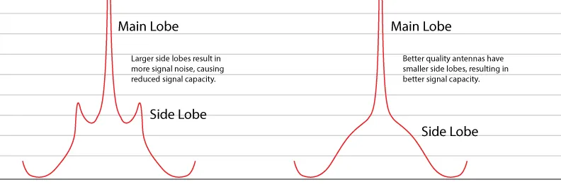
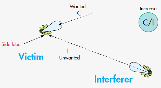
Microwave antennas are intended to be directional. The maximum radiation is thus in the direction of propagation. In practice, it is impossible to shape all the energy in this direction. Some of it spills out off the side and back of the antenna. Due to the complex phases set up in an antenna pattern, lobes result. The main lobe is around the center of the antenna. Side lobes of lesser amplitude result around the rest of the antenna. The aim of a directional antenna is to maximize the energy in the main lobe by minimizing the energy in the side lobes. It is important to understand the radiation patterns when panning antennas to make sure that one does not pan the signal onto a side lobe.
When the radiation signal strength is measured, a main lobe will indicate the main direction of the signal beam. This main lobe indicates the direction the signal will be effectively transmitted. The size of the lobes representing the strength of the signal will decrease as they get further from the main beam. Side lobes appear as small surges in signal radiation adjacent to the main beam. These side lobes can result in unwanted signal noise which can also reduce the antenna’s carrier signal.
Side lobes are unwanted peaks in signal radiation that occur off-axis from the main beam of an antenna. While always lower than the main beam, they can cause interference with other signals operating on the same frequency, degrading overall performance.
Side lobes can vary in size and direction depending on the antenna design and frequency. Lower side lobes are desirable as they indicate better suppression of unwanted signals and improved isolation between systems.
Side lobes that breach the antenna RPE are particularly problematic, indicating a poorly performing antenna with potentially significant interference issues. Manufacturers aim to minimize side lobes through careful design and optimization techniques.
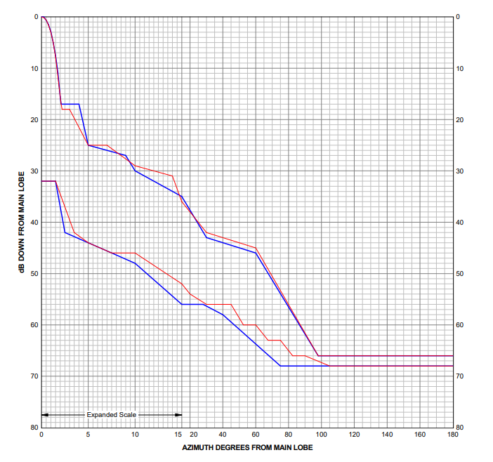
The RPE is basically the guaranteed maximum signal level at a specified angle. Both the angle and the signal level are measured relative to the antenna main beam.
In microwave antenna radiation pattern envelopes (RPEs), measurements are taken for both parallel-polarized (HH, VV) and cross-polarized (HV, VH) signals. These measurements capture the antenna’s response to different signal orientations, which is crucial for understanding its performance.
Parallel-polarized measurements: (HH, VV) represent the intended signal transmission between the antenna and the receiver. High values in these measurements indicate efficient signal transfer.
Cross-polarized measurements: (HV, VH) show how much unwanted signal energy leaks from the antenna in an undesired polarization. Low values in these measurements are important for minimizing interference with other systems.
High-performance antennas often exhibit with lower side lobes on one side of the main lobe. These antennas may have a “superior side” with significantly better performance, highlighting the importance of full 360-degree RPEs for optimal placement and interference management.
RPEs offer a simpler way to visualize the antenna’s radiation characteristics compared to detailed radiation pattern plots. They are particularly useful for:
Antenna selection: Comparing RPEs of different antennas helps choose the one that best suits the desired coverage area, directivity, and interference mitigation needs.
Link design: RPEs allow engineers to predict signal strength at receiver locations and assess potential interference issues in communication links.
Regulatory compliance: Antenna manufacturers provide RPE information to ensure their products comply with regulations on signal emissions and spectrum usage.
For example, a directional antenna like a microwave backhaul antenna will have an RPE with a well-defined main lobe ideally aligned with the link path, smaller side lobes in adjacent directions, and back lobes indicating signal energy lost to the rear.
All the measured patterns are brought together into a single display, which is made available to the market in the form of a radiation pattern envelope (or RPE). The RPE is a straight line segmented graphical representation of the measured radiation patterns and includes margin to accommodate variations due to manufacturing tolerances. Although this envelope approach is quite conservative, it is has been proven to be much more reliable for link planning compared to using discrete (individual) radiation patterns.
Better antennas produce a better signal by creating minimal side lobes which reduces signal noise and increases the signal capacity. Antennas of lesser quality which have larger side lobes which diminish the antenna’s signal capacity.
An antenna’s RPE is normally compared against major regulatory requirements, which govern what antennas can be deployed in certain regions or countries. These organisations include the European Telecommunications Standards Institute (ETSI) and the Federal Communications Commission (FCC) in the USA. There may also be local regulatory specifications that antennas need to meet before they can be deployed.
Carrier Power, Noise and Interference.
In point-to-point communication systems, ensuring reliable and efficient data transmission depends on the received signal level (RSL) or carrier power (C) reaching the receiver accurately. However, interference (I), including background noise and signals from other sources, can disrupt this process.
RSL refers to the strength of the received signal measured at the antenna port of a radio receiver. It is typically expressed in negative decibels relative to milliwatts (dBm), providing a convenient way to represent wide ranges of signal strengths. For example, an RSL of -60 dBm indicates a much weaker signal than -20 dBm.
Signal-to-noise ratio (SNR), the ratio of C to noise power (N), is a crucial factor in communication quality.
Signal-to-noise ratio (SNR) is a key parameter indicating the quality of a received signal, measured in dB as the ratio between the desired signal level and the background noise level. It reflects the demodulator’s ability to differentiate the desired signal from unwanted noise and is crucial for reliable data decoding.
The carrier-to-interference (C/I) ratio, measured in dB, compares the strength of a desired signal (C) to the interfering signals (I) received by a receiver. These interferers can come from other users on the same frequency (co-channel), nearby frequencies (adjacent channel), or even environmental factors like rain or wind.
Shannon’s Law describes the theoretical limit for data transmission capacity in a communication channel, considering bandwidth and signal-to-noise ratio (SNR). It states that the capacity (C) is proportional to the channel bandwidth (B) and the logarithm of one plus the ratio of carrier power (C, often equivalent to received signal level) to noise power (N):
Capacity = B x Log2 (1 + C/N)
Where:
B = Channel bandwidth: This refers to the range of frequencies used for transmission. A wider bandwidth allows for more data to be sent simultaneously, increasing potential capacity. In microwave systems, bandwidth is often allocated according to specific bands and regulations.
C = Carrier power, or RSL.
N = Signal noise.
Today’s communication systems face additional challenges due to interference (I) from other users and sources. Modifying the equation to account for both noise and interference, we get:
Capacity = B x Log2 (1 + C/(N + I))
A higher carrier-to-interference ratio (C/I) indicates a stronger desired signal compared to interference, leading to more efficient transmission, higher data rates, and ultimately, potential for greater revenue. Conversely, neglecting C/I can significantly decrease capacity and lead to customer churn due to poor service quality.
Improving the C/I Ration and Regulatory Compliance.
To arrive at a better C/I ratio, it’s intuitive that one must increase C or reduce I. There are several ways to accomplish each.
To increase C, one can:
Boost transmission power: This is the most obvious way to increase carrier signal, but it comes with added energy costs and is limited by regulatory and interference constraints.
Increase gain with a bigger antenna: Bigger antennas mean more capacity, but they are expensive to ship, install and maintain, plus, tower space and loading allowances may not allow them at all in some places.
To decrease I, one can:
Use a different frequency: This can help avoid specific interference problems, but spectrum is extremely limited and this is not always a viable option.
Use a different link path: Realigning an antenna to route signal around a problem is sometimes possible, but overall cost factors prevent this from being a reliable large-scale solution.
Use an antenna with smaller side lobes: Since the RPE of an antenna determines its resistance to interference, the lower the side lobes, the less likely it is for interference to find its way into the signal.
Well-engineered antennas with lower side lobes deliver tangible benefits beyond just technical performance.
- Boost revenue potential: Increased link capacity thanks to higher modulation schemes can support more users and higher data rates, driving revenue growth. For example, using QAM-256 instead of QAM-64 with lower interference could potentially increase data rates by 4x.
- Reduce operational costs: Smaller antennas mean lower shipping, installation, and tower lease costs. Estimates suggest these savings can reach up to 30% compared to traditional antennas.
- Simplify network management: Less interference simplifies coordination and planning, saving time and resources. Fewer site visits for maintenance due to interference issues further reduce operational expenses.
- Conserve valuable spectrum: Efficient spectrum reuse through lower side lobes allows you to maximize your spectrum investment and accommodate more subscribers with limited resources.
I suggest exploring the presentation Improving Microwave Capacity by Aviat Networks that explain how to improve microwave radio capacity by understanding techniques that improve throughput.
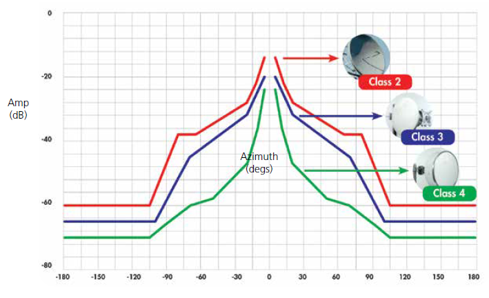
Tighter control of an antenna’s RPE means less likelihood of causing or receiving interference. Since the RF spectrum is regulated, there are specific classifications for antennas displaying different RPEs.
Bodies such as the European Telecommunications Standards Institute (ETSI) in the European Union and the Federal Communications Commission (FCC) in the United States publish standards that all antennas must meet in order to comply with regulatory requirements. For example, ETSI classifies four different microwave antenna standards, called Class 1, Class 2, Class 3 and Class 4, in order of ascending stringency of permissible RPE.
In the United States, the FCC maintains its own RPE standards for directional antennas, called Category A and the less stringent Category B. Other countries and regions have similar regulations.
In all cases, however, the conclusion is the same: higher-quality antennas with lower side lobes and tighter RPE characteristics yield better performance, better TCO, and better regulatory compliance.
The RPE of a microwave antenna is the key to understanding how it will operate in the real world under working conditions. The size of the RPE’s side lobes can be an accurate predictor of how much of an issue interference will be—and what the corresponding capacity reduction will mean to the network and to the business itself.
A compliant, high-performance antenna with low side lobes offers significant advantages on both technological and financial levels. Because it reduces interference, it keeps network capacity optimized; and, because it also reduces TCO (*), it keeps an operator’s balance sheet optimized.
(*) Total cost of ownership: In this instance, a holistic calculation of all costs involved in an antenna deployment, including purchase price, energy use, maintenance costs and time expenditure, among other factors.
Up to this point, we’ve covered Part 2 of Microwave Communications Basics. Stay tuned for the upcoming articles where we will delve into other topics within this domain.
Bibliography:
Link budget: Link budget
RF Planning: RF Planning
Line-of-sight propagation: Line-of-sight propagation
Free-space path loss: Free-space path loss - Wikipedia
Free Space Path Loss: details & calculator: Free Space Path Loss: Details & Calculator » Electronics Notes
Atmospheric radiation, an online guide: Atmospheric Radiation, an online guide by Severewx.com
Electromagnetic absorption by water: Electromagnetic absorption by water - Wikipedia
Energy and Radiation, Selective Absorption by the Atmosphere: thephysicalenvironment.com/Book/energy/atmospheric_absorption.html
Recommendation ITU-R P.530: Recommendation ITU-R P.530 — ITU-Rpy 0.4.0 documentation
What are Key Types of Microwave Antennas and What are They Used For?: What are Key Types of Microwave Antennas and What are They Used For? - Rantec Microwave Systems
Notes on Microwave propagation and Space-Diversity: https://bryanfields.net/mw-papers/
EEVblog Electronics Community Forum, Antenna Radiation Patterns Explained: Antenna Radiation Patterns Explained - Page 1
Microwave Antenna Performance Metrics: Microwave Antenna Performance Metrics | IntechOpen
The Increasing Importance of Microwave Antenna Radiation Pattern Envelopes: The Increasing Importance of Microwave Antenna Radiation Pattern Envel | CommScope
In Microwave, It’s All About the Pattern: In Microwave, It’s All About the Pattern | CommScope
Radiation Pattern Envelope by ETI Staff: Radiation Pattern Envelope - ETI
REPORT & TUTORIAL CARRIER-TO-INTERFERENCE OBJECTIVES: https://nsma.org/wp-content/uploads/2016/05/wg5-92-08.pdf
Planning a Microwave Radio Link: file:///C:/Users/44777/Desktop/ydi_microwavelink.pdf