A modern wireless network depends on multiple systems, meshing together, to provide the customer with a positive experience. Microwave communications, used for backhaul applications that move site traffic on and off of the core network, can make or break that positive customer experience.
Let’s explore some common terms.
Microwave backhaul: The use of microwave communications to aggregate and transmit cellular voice and data to and from the main network.
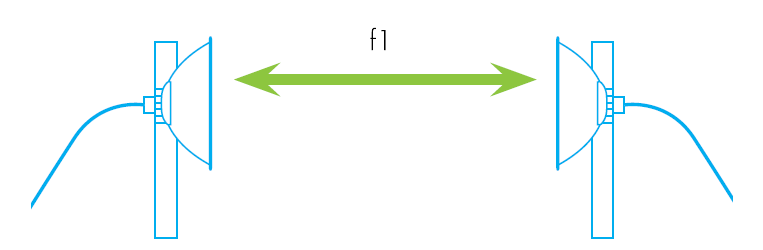
Within the broader spectrum of radio frequency (RF) communications, point-to-point communications are usually carried out using microwave frequencies between 1 GHz and 100 GHz (*) along line-of-sight (LOS) paths called links. (**)
(*): It’s not the absolute limit. Some systems operate at even higher frequencies, up to 300 GHz or even beyond, especially for shorter-range applications.
(**): While LOS is crucial for many microwave links, it’s not always the only possibility. Some systems employ techniques like near-LOS or non-LOS propagation strategies for specific situations where direct line-of-sight is challenging.
These frequencies and their propagation characteristics allow the transmission of vast amounts of data between remote communication sites without the need to lay cables between them.
Line of sight (LOS): A clear path, free of any obstructions, between points of microwave signal transmission and reception.
Near-Line-of-Sight (nLOS): Describes a “partially obstructed path between the location of the signal transmitter and the location of the signal receiver." Obstacles that can cause an obstruction in the line of sight include trees, buildings, mountains, hills and other natural or man-made structures or objects.
Non-Line-of-Sight (NLOS): NLOS encompasses any situation where the path between the transmitter and receiver is completely blocked.
Microwave Link: A point-to-point communication connection between two fixed sites using line-of-sight (LOS) within the microwave frequency range. While LOS is preferred, some systems can operate in near-LOS or non-LOS conditions with specialized techniques. Microwave links offer the advantage of high bandwidth and long-range communication, but their performance can be affected by terrain obstacles and weather conditions. The term “hop” is also often used, particularly when referring to multiple links used to establish longer-range communication paths.
Key performance indicators (KPI): Critical measurements of network function related to reliability and performance.
Network operators continually monitor key performance indicators (KPIs) within their networks to identify performance problems and ensure customer satisfaction. These indicators include quality of service (QoS), link failures, lost traffic, and other criteria.
Microwave bands.
The microwave spectrum is usually defined as a range of frequencies ranging from 1 GHz to over 100 GHz. (*) This range has been divided into a number of frequency bands, each represented by a letter. There are a number of organizations that assign these letter bands. The most common being the IEEE Radar Bands followed by NATO Radio Bands and ITU Bands.
(*) : In some contexts, it may extend up to 300 GHz. The specific range can vary based on different applications and standards. Discussions or classifications might consider frequencies up to 300 GHz in certain cases. The actual range can depend on the industry or organization defining it.
Below you can see a table with details on each letter band.
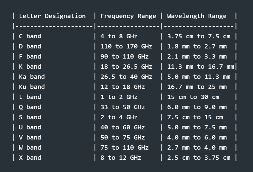
Click on the letter band to learn more about it: C, D, F, K, Ka, Ku, L, Q, S, U, V, W, X.
I suggest exploring the article Microwave Frequency Bands: Applications and Advantages for additional insights and information.
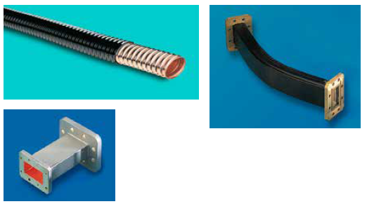
Waveguide.
Waveguide: A metallic-sheathed physical transmission medium; unlike a cable, waves propagate along it without an inner conductor.
Microwave energy travels in different ways through guided paths. Think of a microwave waveguide with a single conductor as a sort of filter that only allows certain frequencies to pass through, these structures have a cutoff frequency.
Microwave waveguides are maintained under dry air or dry nitrogen pressure to avoid moisture condensation that would impede their performance.
More about waveguides in future articles.
The Signal.
Modulation: The practice of encoding large amounts of data onto a carrier signal to allow transmission.
The wireless network’s traffic is extracted from the mobile telephone frequency band carrier and coded, aggregated and compressed into a relatively small radio channel. This is aided by a technique called modulation.
The radio channel is up-converted to the correct microwave frequency and transmitted across a link to a receiver station, which then down-converts and demodulates the signal to extract its aggregated information so it can be sent along to its final destination.
Channel Capacity: The capacity of a communications channel is directly proportional to its bandwidth and the modulation scheme used. This means wider channels and more efficient modulation techniques can transmit more data in a given amount of time.
FDD Systems: Frequency-division duplexing (FDD) is a method for enabling simultaneous two-way communication over a single frequency band. It accomplishes this by allocating separate sub-bands within the band for upstream (go) and downstream (return) transmissions. This is typically visualized as a “go/return pair”.
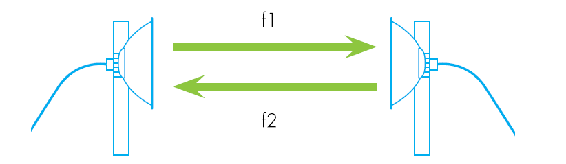
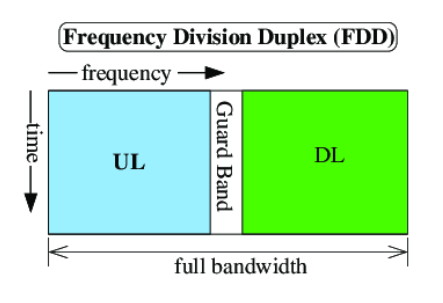
Microwave backhaul links often rely on FDD because it facilitates simultaneous communication without requiring complex switching mechanisms or additional infrastructure. This improves efficiency and overall throughput of the backhaul connection. FDD is currently the dominant mode of operation in microwave backhaul systems. This is due to its advantages in terms of simplicity, reliability, and compatibility with existing infrastructure.
TDD Systems: Time-division duplex (TDD) is another way of achieving two-way communication, it operates on a single channel by alternating transmission directions using precise timing synchronization.
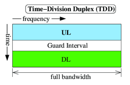
Compared to FDD, TDD offers higher spectral efficiency because it doesn’t require dedicated sub-bands for each direction. However, it comes with drawbacks:
Challenges of TDD in Microwave Backhaul:
- Strict Timing Control: Accurate synchronization is crucial in TDD to avoid data collisions and ensure smooth transitions between transmission directions. This can be challenging in long-distance microwave links due to potential signal delay variations.
- Latency Concerns: Switching between transmit and receive modes introduces unavoidable latency in TDD, which can be problematic for real-time applications like voice or video calls.
- Equipment Complexity: Implementing TDD requires more complex hardware and software compared to FDD, potentially increasing cost and maintenance needs.
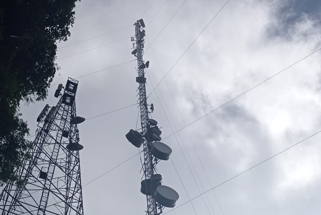
Microwave Antennas.
Aperture antennas find their primary application in microwave frequencies, characterized by a significant physical area or aperture. Reflectors, another prevalent design, are commonly employed at both microwave and millimeter-wave (MMW) frequencies. Additional antenna types suitable for these frequency ranges include array antennas, horn antennas, and lens antennas.
- Aperture antennas: Their large physical area makes them efficient radiators at microwave frequencies, ideal for long-range communication and power transmission.
- Reflector antennas: Utilizing parabolic dishes, they excel at focusing signals for both microwave and MMW applications, like satellite communication and radio astronomy.
- Array antennas: Combining multiple smaller elements, they offer electronically steerable beams and are valuable in radar and satellite tracking systems.
- Horn antennas: Functioning like megaphones for electromagnetic waves, they provide focused beams for applications like radar, medical imaging, and material testing.
- Lens antennas: Employing specially designed lenses, they manipulate and shape the signal path, gaining approval in satellite communication and imaging systems.
Microwave propagation through the atmosphere.
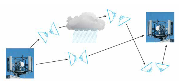
By its nature, microwave transmission is exposed to environmental and weather variables. Depending on its location, an antenna may be subjected to rain, hail, snow, fog, temperature extremes and dangerously high winds—not to mention exposure to lightning strikes.
Poor environmental conditions can disrupt microwave links, as signal reflection or refraction can greatly reduce the power levels of received signals. This is true particularly of higher-frequency transmissions, which are more susceptible to weather effects. In addition, adjacent-link interference can be a problem if there is not sufficient LOS clearance.
Impact of specific weather conditions:
- Rain: Heavy rain can cause significant attenuation (signal weakening) due to absorption and scattering of the waves.
- Hail: Large hail can physically damage antennas and disrupt the signal path.
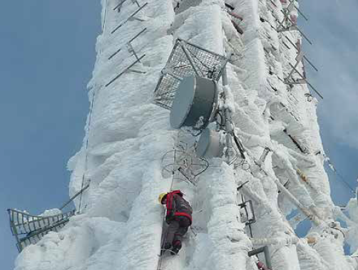
- Snow: Wet snow can accumulate on antennas, increasing weight and potentially causing structural damage.
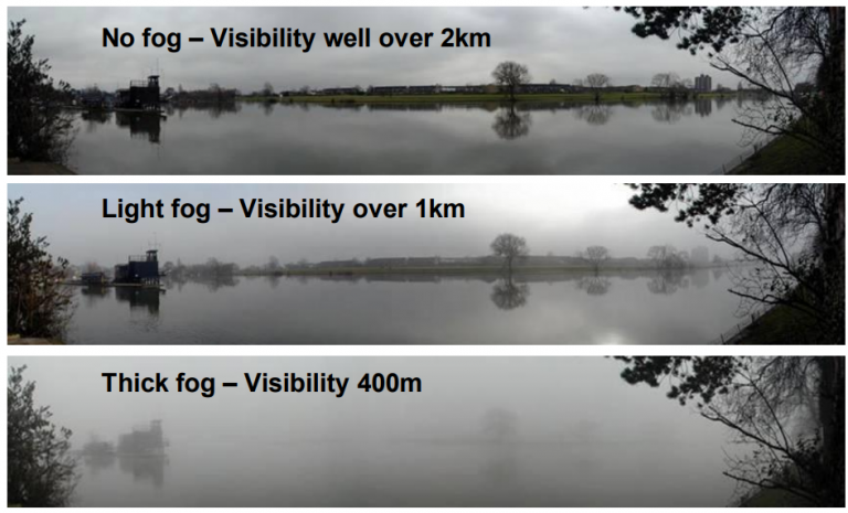
- Fog: Dense fog can act like a wall, effectively blocking the line-of-sight path for the signal.
- Temperature extremes: Extreme hot or cold temperatures can affect antenna performance and stability.
- Wind: High winds can cause antenna movement and misalignment, impacting signal quality.
Impact of the Atmosphere on RF Signal Propagation.
As we go higher up in frequency, the earths atmosphere starts to impact the propagation of RF signals. RF signals travelling in free space are effected by atmospheric attenuation. This attenuation in the atmosphere is caused mainly by signal absorption by gasses such as O2 and H2O. The effect of signal absorption under 10 GHz is fairly low and predictable, however as we go higher in frequency (specially in to the mm-Wave range i.e 30 to 300 GHz) this attenuation increases significantly, specially at certain frequencies. The attenuation is not only increases but also becomes more dependent on the absorbing characteristics of H2O, O2 and other gasses.
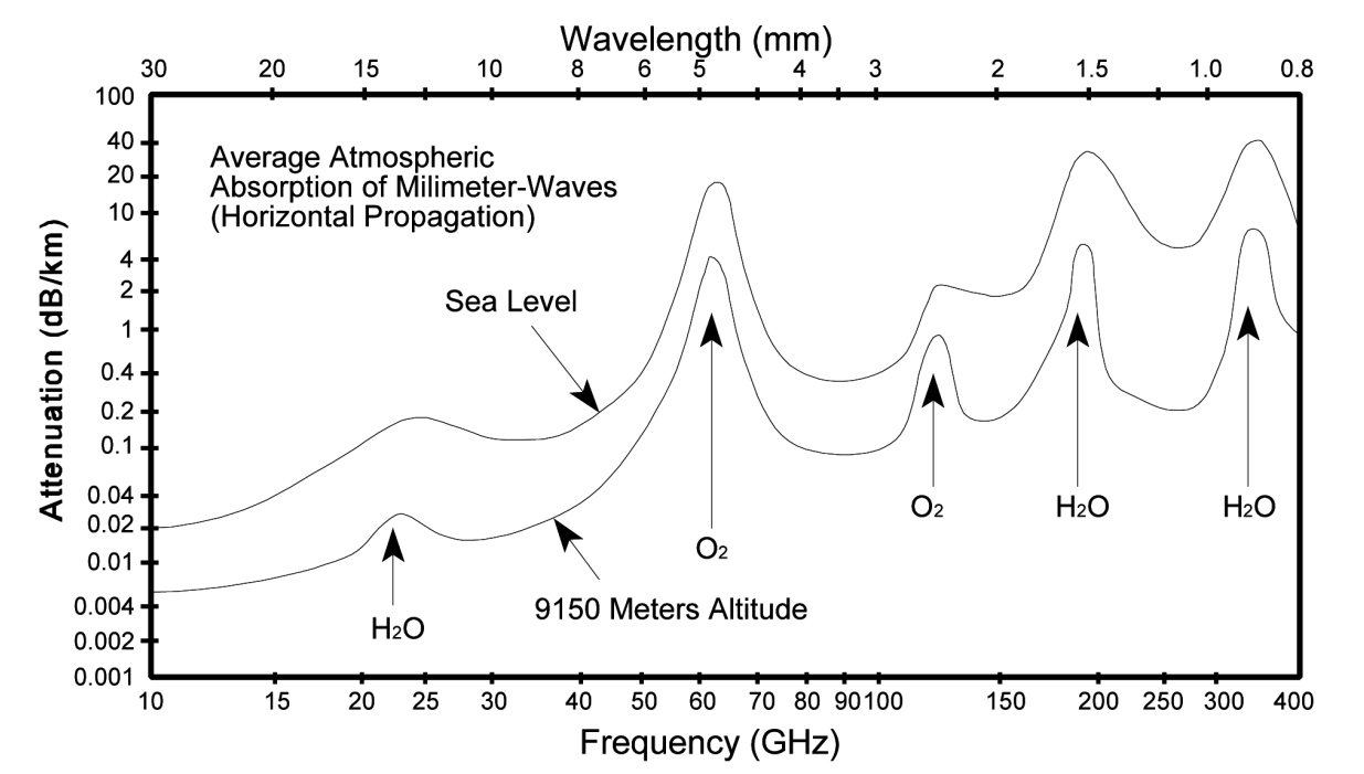
As can be seen in the chart above, the attenuation is maximum in a few frequency bands, mainly those of oxygen at 60 GHz and water vapor at 24 GHz and 184 GHz. There are a number of frequency windows where atmospheric attenuation is significantly lower. It is in these gaps where most applications in the mm-Wave frequency bands operate.
Making a long hop with a lower frequency.
Fade: Loss in signal strength across a link caused by atmospheric disturbances like rain or snow that can scatter microwave signals.
The microwave bands at lower frequencies provide the potential for longer-distance communication, theoretically allowing links of over 50 km (31 miles). However, the practical link length is determined by factors such as traffic fidelity, especially in challenging weather conditions. For instance, even light rainfall can introduce signal losses, resulting in a phenomenon called “fade” where the signal strength diminishes across the channel.
To account for these effects, engineers employ established “rain outage models” that predict the expected signal attenuation during specific rainfall rates. With this information in hand, link designers incorporate a performance safety margin, typically in the form of an additional power budget. This ensures that the link operates within specifications, even in adverse weather conditions. This safety margin is achieved through Adaptive Transmit Power Control (ATPC), a system that dynamically adjusts power levels to compensate for any impediments in the link, maintaining signal fidelity.
ATPC is required to ensure high availability in fog and other atmospheric events.
ATPC works like this:
- Continuously monitors the signal strength on the link.
- Detects a decrease in signal.
- Automatically adjusts the transmitter power, boosting it to compensate for the signal loss caused by the fog.
- In essence, ATPC acts as a dynamic dimmer switch, ensuring the signal remains strong and the data flows uninterrupted, even as the fog rolls in.
Higher frequencies, higher attenuation.
For frequencies exceeding 11 GHz, challenges posed by rain and other weather phenomena become more pronounced. Simply increasing signal power is insufficient, and adjustments to the link’s length may be necessary. Rain or snow-induced signal scattering can be countered with Adaptive Transmit Power Control (ATPC) and by limiting the link’s length. Another effective approach involves signal polarization, the orientation of the signal’s wave concerning the ground.
Signals can be vertically or horizontally polarized, with horizontally polarized signals being more susceptible to rain due to the shape of falling raindrops. Hence, vertical polarization is often a better choice for link planning. However, raindrops can cause polarization rotation during their fall, potentially leading to interference with other polarized signals in the channel. Cross-polar interference cancellers (XPICs) address this issue by sampling signals in both polarizations and creating a cancelling routine for any interference.
Adaptive modulation is another strategy to counteract atmospheric attenuation. Adaptive modulation allows the signal to dynamically adjust its modulation based on changing conditions, reducing modulation for better fidelity in poor conditions and increasing it to maximize capacity in clear conditions.
A more strategic solution involves employing a multi-hop topology or arrangements of links in the network. Mesh and ring topologies offer alternative paths, ensuring optimal connectivity. During adverse weather conditions affecting one link, the network can bypass the affected path by routing through another, thereby maintaining continuous and reliable connectivity.
Other atmospheric challenges.
Fog Impact: Typical fog with low water density may have minimal impact on lower microwave frequencies, however, high-density fog at any frequency, or even light fog at millimeter-wave (mmWave) frequencies above 60 GHz, can cause significant attenuation and disrupt signal quality.
Air Temperature: Air temperature itself has minimal direct impact on microwave transmission. However, sudden temperature drops can indeed lead to condensation in waveguides, especially if they contain residual moisture. This condensation mimics the effects of rain, causing attenuation and potentially disrupting the link.
Using pressurized dry air or nitrogen to keep moisture out of waveguides is a common and effective method to prevent condensation. However, it’s not the only approach. Other methods like dehumidifiers, heating elements, and specially designed waveguides with minimized water traps can also be employed.
Climate not only impacts signal strength and fidelity but also takes a toll on the physical integrity of the microwave infrastructure. Accumulation of snow and ice on exposed antenna structures can increase weight on the mounts, requiring consideration in the total weight calculation for antennas and equipment.
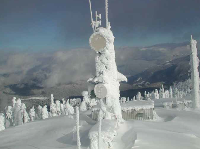
To mitigate this, antennas can be equipped with protective covers, known as radomes, which prevent the build-up of snow and ice in front of the antenna while also reducing wind load. Radomes are especially beneficial for large, long-haul microwave antennas, which are already heavy and susceptible to high wind loads. Additionally, ice shields can be applied to prevent damage to antennas caused by falling ice from above. These measures ensure the resilience and reliability of the microwave infrastructure under challenging weather conditions.
Bibliography:
Line of Site, LOS, Near Line of Site, nLOS, Non Line of Site, NLOS - Definitions etc: Line of Site, LOS, Near Line of Site, nLOS, Non Line of Site, NLOS - Definitions etc - PMP - Cambium Community
Atmospheric Absorption (Specific Attenuation): Atmospheric Absorption (Specific Attenuation) Chart - RF Cafe
Atmospheric Attenuation: https://propagation.ece.gatech.edu/ECE6390/project/Fall2012/Team09/Team9GeoSatTech_website_FINAL/SatCom%20website/atmosphericAttenuation.html
FSO: Automatic Transmit Power Control (ATPC): https://www.cablefree.net/wirelesstechnology/free-space-optics/fso-automatic-transmit-power-control-atpc/
ATPC: Automatic Transmit Power Control: ATPC: Automatic Transmit Power Control - CableFree
Scenario RF Environment Properties: The RF Environment - Scenario Environment Properties
Back to Basics in Microwave Systems: Cross-Polar Discrimination: 2014 | CommScope
XPIC – Cross Polarization Interference Cancellation: XPIC - Cross Polarisation Interference Cancellation - CableFree
XPIC cross polarization interference cancellation: XPIC cross polarization interference cancellation