Switch forwards the data packets within the same local network. The data packets forwarded by switch on the basis of MAC table which is stored in its operating system. The basic functionality of switch is to forward the data packets to its destination by MAC filtering.
Layer 2 switch connects two or more different devices within a local area network. Switch works like a relay for data transfer between end devices. When the destination of a data packet is beyond the LAN, the packet forwarded to the gateway router.
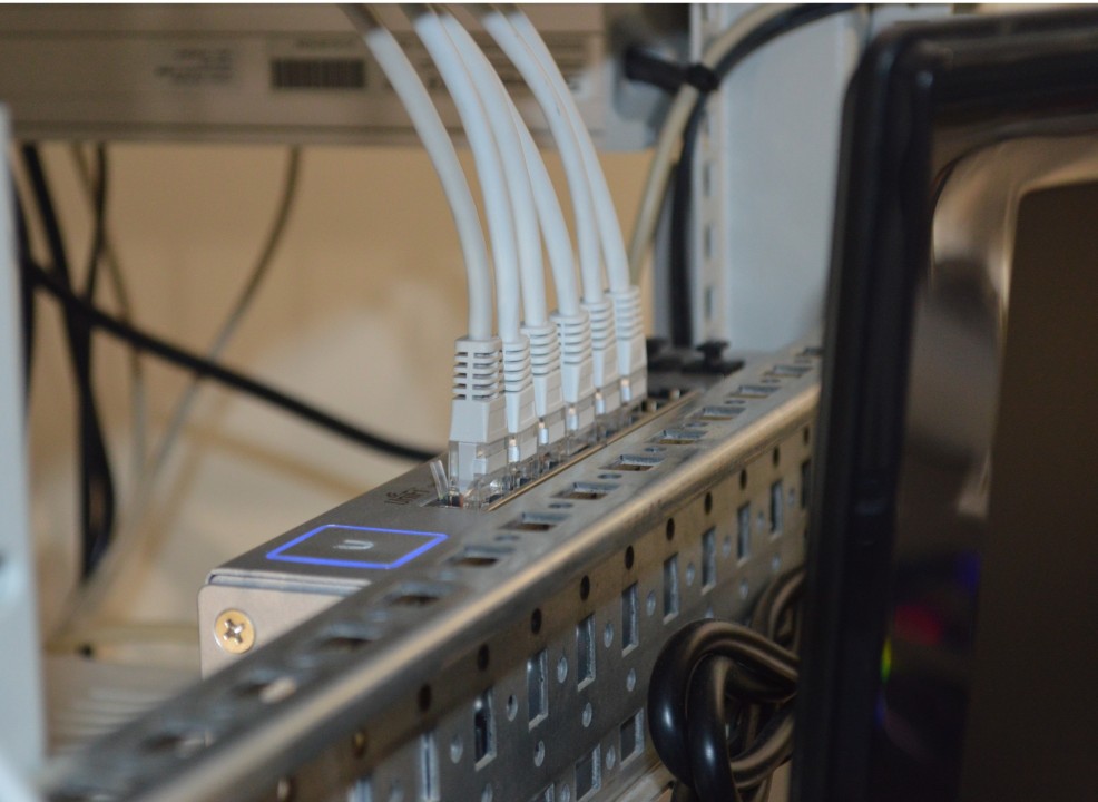
Role of a Switch in a network.
A Switch is a networking device which works at Data Link layer in networking. A Switch receive and transmit the data packets between different end devices. We can say the Layer 2 switching basic concepts are related to receive and transmit the data packets in a network.
When a network switch receives a frame, it examines the destination MAC (Media Access Control) address within the Ethernet frame header. The switch maintains a MAC address table, associating MAC addresses with specific switch ports. If the destination MAC address is found in the table, the switch efficiently forwards the frame solely to the port where the device with that MAC address is connected. Notably, switches operate at the data link layer (Layer 2 of the OSI model) and are oblivious to IP addresses, focusing exclusively on MAC addresses for local network frame forwarding. In the event that the destination MAC address is not present in the table, the switch employs a mechanism similar to a hub, broadcasting the frame to all other ports (excluding the incoming port), facilitating the device with the correct MAC address to respond and update the table.
The main purpose of a switch is to make a LAN work better, to optimize its performance, providing more bandwidth for the LAN’s users. And switches don’t forward packets to other networks as routers do. Instead, they only “switch” frames from one port to another within the switched network.
By default, switches break up collision domains. This is an Ethernet term used to describe a network scenario where in one particular device sends a packet on a network segment, forcing every other device on that same segment to pay attention to it. If at the same time a different device tries to transmit, leading to a collision, both devices must retransmit, one at a time.
Layer 3 machines (such as routers) need to locate specific networks, where as layer 2 machines (switches and bridges) need to eventually locate specific devices. So, networks are to routers as individual devices are to switches and bridges. And routing tables that “map” the internetwork are for routers as filter tables that “map” individual devices are for switches and bridges.
The biggest benefit of using switches instead of hubs in your internetwork is that each switch port is actually its own collision domain. (Conversely, a hub creates one large collision domain.) But even armed with a switch, you still don’t break up broadcast domains by default. Neither switches nor bridges will do that. They’ll simply forward all broadcasts instead.
Layer 2 Discovery Protocols: CDP and LLDP.
Layer 2 discovery protocols are used to learn about neighbouring devices on a network. Two of the most common protocols are Cisco Discovery Protocol (CDP) and Link Layer Discovery Protocol (LLDP). Both protocols have their own strengths and weaknesses.
Both protocols can be used to detect the presence of other devices and to collect various pieces of information about them, such as the device’s name, model, and operating system.
CDP is a proprietary protocol that is specific to Cisco devices, while LLDP is an industry-standard protocol that can be used with any type of device.
What are Layer 2 Discovery Protocols ?
- Layer 2 discovery protocols such as CDP and LLDP share information with and discover information about neighbouring devices that are connected to each other.
- They are called ‘Layer 2’ discovery protocols because the protocols themselves operate at Layer 2. They do not use IP addresses.
- This means that there are no IP packets inside the frames sent by CDP and LLDP in a network.
- They can also be used to share Layer 3 information such as IP addresses.
- The shared information consists of a host name, IP address, device type, etc.
- CDP is a Cisco proprietary protocol developed for Cisco devices by Cisco itself.
- LLDP is an industry-standard protocol (IEEE 802.1AB).
- Therefore, if your network is a mix of vendors such as Juniper switches, Cisco routers, and Palo Alto firewalls, you will need to use LLDP as your Layer 2 discovery protocol in your network.
- Since these protocols share information about the devices in a network, they are considered a security risk and are often not used. It depends on the Network Engineer/Administrator to decide if he wants to use them in the network or not.
CDP (Cisco Discovery Protocol):
CDP is a Cisco proprietary protocol that has been around for a long time. This protocol is used for discovering information about Cisco devices on the network.
CDP can tell you what type of device it is, what version of IOS it is running, and even what type of interfaces the device has. CDP has the advantage of being included in most Cisco devices. This means that you don’t have to configure anything in order to use CDP.
It also has the advantage of being able to tell you a lot of detailed information about the device. This can be useful for troubleshooting and monitoring the network. However, the biggest downside of CDP is that it is proprietary and only works with Cisco devices. This means that if you have any devices from other vendors, CDP won’t work.
To view the CDP neighbors on a Cisco switch and gather information about the network topology, you can use the following command in the switch’s command-line interface (CLI):
show cdp neighbors
This command will display a list of directly connected devices discovered through CDP, along with details such as the neighboring device’s hostname, local interface, and platform information.
Additionally, you can use the following extended command to get more detailed information:
show cdp neighbors detail
This command provides a more comprehensive output, including information about the capabilities, IP addresses, and version of the neighboring devices.
LLDP (Link Layer Discovery Protocol):
LLDP is a standards-based protocol that is used by many different vendors. It is similar to CDP in that it is used to discover information about other devices on the network. However, the big difference is that LLDP is designed to be compatible with all vendors.
This means that you can use it to discover information about devices from any vendor, not just Cisco. Like CDP, LLDP is a good protocol for troubleshooting and monitoring the network.
It is also relatively easy to configure and configure. The downside of LLDP is that it doesn’t provide as much detail as CDP. It can tell you what type of device it is and what type of interfaces it has, but not what version of IOS it is running.
To view LLDP neighbors on a Cisco switch, you can use the following command:
show lldp neighbors
or
show lldp neighbors detail
for additional information about the neighboring devices.
CDP and LLDP: Security Implications.
These protocols can be used by attackers to map out the network by discovering the relationships between devices. This information could aid in planning targeted attacks or unauthorized access.
Information provided by these protocols can be used to identify the types and models of devices on the network. This knowledge can be valuable for planning attacks that specifically target vulnerabilities associated with certain device types.
To enhance security, consider the following measures:
Disable CDP or LLDP if Not Needed: If these protocols are not required for network management or specific functionalities, consider disabling them on network devices.
To disable CDP or LLDP on a Cisco switch, you can use the following commands:
Switch(config)# no cdp run
This command globally disables CDP on the switch. If you want to disable CDP on a specific interface, you can do so with the following command:
Switch(config-if)# no cdp enable
Disable LLDP:
Switch(config)# no lldp run
This command globally disables LLDP on the switch. To disable LLDP on a specific interface, you can use:
Switch(config-if)# no lldp transmit
Switch(config-if)# no lldp receive
Switch(config-if)# no lldp med
These commands disable LLDP transmission, reception, and media endpoint discovery on the specified interface.
Implement VLANs: Use VLANs to segment the network, limiting the scope of CDP and LLDP information to specific segments.
Filtering and Access Control: Implement access control lists (ACLs) or filters to restrict the devices that can send or receive CDP and LLDP packets
Collision Domain and Broadcast Domain in Computer Network.
Difference between a hub, a bridge, a switch, and a router. Hubs create one collision domain and one broadcast domain. Bridges break up collision domains but create one large broadcast domain. Switches are really just multiple-port bridges with more intelligence. They break up collision domains but create one large broadcast domain by default. Switches use hardware addresses to filter the network. Routers break up broadcast domains (and collision domains) and use logical addressing to filter the network.
Collision Domain:
A Collision Domain is a scenario in which when a device sends out a message to the network, all other devices which are included in its collision domain have to pay attention to it, no matter if it was destined for them or not. This causes a problem because, in a situation where two devices send out their messages simultaneously, a collision will occur leading them to wait and re-transmit their respective messages, one at a time. Remember, it happens only in the case of a half-duplex mode.
Layer 2 Switching and Collision Domains.
Layer 2 switching occurs at the Data Link layer, where data transfer relies on the utilization of MAC addresses associated with devices. The primary function of a Layer 2 switch is to effectively break down collision domains within a network. Each port on a Layer 2 switch establishes its own collision domain, ensuring efficient and simultaneous data transfer.
A collision domain is, as the name implies, the part of a network where packet collisions can occur. A collision occurs when two devices send a packet at the same time on the shared network segment. The packets collide and both devices must send the packets again, which reduces network efficiency. Collisions are often in a hub environment because each port on a hub is in the same collision domain. By contrast, each port on a bridge, a switch, or a router is in a separate collision domain.
Broadcast Domain:
A Broadcast Domain is a scenario in which when a device sends out a broadcast message, all the devices present in its broadcast domain have to pay attention to it. This creates a lot of congestion in the network, commonly called LAN congestion, which affects the bandwidth of the users present in that network.
Difference between a collision domain and a broadcast domain. Collision domain is an Ethernet term used to describe a network collection of devices in which one particular device sends a packet on a network segment, forcing every other device on that same segment to pay attention to it. On a broadcast domain, a set of all devices on a network segment hear all broadcasts sent on that segment.
Reducing collision domains does improve network efficiency because it minimizes the likelihood of collisions. Switched networks, by creating separate collision domains per port, enhance efficiency compared to shared segments or hubs.
Increasing the number of broadcast domains does not necessarily improve bandwidth for individual users. Broadcast traffic can still consume network resources, and careful network design is required to manage broadcast domains effectively.
Layer 2 Switching and Spanning Tree Protocol (STP).
Layer 2 switching is the process of using the hardware address of devices on a LAN to segment a network.
You know that switching breaks up large collision domains into smaller ones and that a collision domain is a network segment with two or more devices sharing the same bandwidth. A hub network is a typical example of this type of technology. But since each port on a switch is actually its own collision domain, you can make a much better Ethernet LAN network just by replacing your hubs with switches!
If you have redundant physical links between your switches, routing protocols won’t do a thing to stop loops from occurring at the Data Link layer. That’s exactly the reason Spanning Tree Protocol (STP) was developed, to put a stop to loops in a layer 2 switched network.
Switching Services.
Layer 2 switches and bridges are faster than routers because they don’t take up time looking at the network layer header information. Instead, they look at the frame’s hardware addresses before deciding to either forward, flood, or drop the frame.
Switches create private, dedicated collision domains and provide independent bandwidth on each port, unlike hubs.
What makes layer 2 switching so efficient is that no modification to the data packet takes place. The device only reads the frame encapsulating the packet, which makes the switching process considerably faster and less error prone than routing processes are.
Plus, layer 2 switching increases bandwidth for each user because, again, each connection (interface) into the switch is its own collision domain.
Limitations of Layer 2 Switching.
Bridged networks break up collision domains, but remember, that network is still one large broadcast domain. Neither layer 2 switches nor bridges break up broadcast domains by default, something that not only limits your network’s size and growth potential, but also can reduce its overall performance.
Broadcasts and multicasts, along with the slow convergence time of legacy spanning trees, can give you some major grief as your network grows. These are the big reasons layer 2 switches cannot completely replace routers (layer 3 devices) in the internetwork.
Switch Functions at Layer 2.
There are three distinct functions of layer 2 switching: address learning, forward/filter decisions, and loop avoidance.
Address learning: Layer 2 switches and bridges remember the source hardware address of each frame received on an interface, and they enter this information into a MAC database called a forward/filter table.
When a switch is first powered on, the MAC forward/filter table is empty. When a device transmits and an interface receives a frame, the switch places the frame’s source address in the MAC forward/filter table, allowing it to remember which interface the sending device is located on. The switch then has no choice but to flood the network with this frame out of every port except the source port because it has no idea where the destination device is actually located. If a device answers this flooded frame and sends a frame back, then the switch will take the source address from that frame and place that MAC address in its database as well, associating this address with the interface that received the frame. Since the switch now has both of the relevant MAC addresses in its filtering table, the two devices can now make a point-to-point connection. The switch doesn’t need to flood the frame as it did the first time because now the frames can and will be forwarded only between the two devices. This is exactly the thing that makes layer 2 switches better than hubs. In a hub network, all frames are forwarded out all ports every time, no matter what.
Forward/filter decisions: When a frame is received on an interface, the switch looks at the destination hardware address and finds the exit interface in the MAC database. The frame is only forwarded out an appropriate destination port.
When a frame arrives at a switch interface, the destination hardware address is compared to the forward/filter MAC database. If the destination hardware address is known and listed in the database, the frame is only sent out the correct exit interface. The switch doesn’t transmit the frame out any interface except for the destination interface. This preserves bandwidth on the other network segments and is called frame filtering.
But if the destination hardware address is not listed in the MAC database, then the frame is flooded out all active interfaces except the interface the frame was received on. If a device answers the flooded frame, the MAC database is updated with the device’s location (interface).
If a host or server sends a broadcast on the LAN, the switch will flood the frame out all active ports except the source port by default. Remember, the switch creates smaller collision domains, but it’s always still one large broadcast domain by default.
Port security:
Unwanted devices, including hosts, hubs, switches, or access points, can potentially connect to switch ports, posing security threats. Default settings may allow MAC addresses to dynamically appear in the MAC forward/filter database, opening avenues for unauthorized access.
Port security is a feature implemented in network switches to control access to individual switch ports. Its primary objective is to restrict the number of MAC addresses allowed on a specific port, thwarting unauthorized devices from connecting.
Using port security, you can limit the number of MAC addresses that can be assigned dynamically to a port.
Port security allows administrators to define static MAC addresses explicitly associated with a port. This ensures that only the designated devices are permitted to connect to that port.
Port security supports various violation modes that dictate the actions to be taken when a violation occurs. Common violation modes include shutting down the port, sending an alert, or restricting further MAC addresses dynamically.
Secure MAC address learning ensures that only authorized MAC addresses are added to the MAC address table. If an unauthorized device attempts to connect, port security can take predefined actions to mitigate the security risk.
Port security allows for dynamic MAC address assignment when a device initially connects to the port. However, the number of dynamically assigned addresses is restricted according to the configured limits.
Loop avoidance: If multiple connections between switches are created for redundancy purposes, network loops can occur. Spanning Tree Protocol (STP) is used to stop network loops while still permitting redundancy.
Redundant links between switches are a good idea because they help prevent irrecoverable network failures in the event one link stops working. Sounds great, but even though redundant links can be extremely helpful, they often cause more problems than they solve. This is because frames can be flooded down all redundant links simultaneously, creating network loops.
Here’s a list of some of the ugliest problems:
- If no loop avoidance schemes are put in place, the switches will flood broadcasts endlessly throughout the internetwork. This is sometimes referred to as a broadcast storm.
- A device can receive multiple copies of the same frame since that frame can arrive from different segments at the same time.
- The MAC address filter table could be totally confused about the source device’s location because the switch can receive the frame from more than one link. And what’s more, the bewildered switch could get so caught up in constantly updating the MAC filter table with source hardware address locations that it will fail to forward a frame.
- Multiple loops generating throughout a network. This means that loops can occur within other loops, and if a broadcast storm were to also occur, the network wouldn’t be able to perform frame switching.
All of these problems must be avoided, or at least fixed somehow. That’s where the Spanning Tree Protocol comes into the game. It was developed to solve each and every one of those problems.
Spanning Tree Protocol (STP):
STP’s main task is to stop network loops from occurring on your layer 2 network (bridges or switches). It vigilantly monitors the network to find all links, making sure that no loops occur by shutting down any redundant links. STP uses the spanning-tree algorithm (STA) to first create a topology database and then search out and disable redundant links. With STP running, frames will be forwarded only on the premium, STP-picked links.
Spanning Tree Terms:
Root bridge: The root bridge is the bridge with the best bridge ID. With STP, the key is for all the switches in the network to elect a root bridge that becomes the focal point in the network. All other decisions in the network, such as which port is to be blocked and which port is to be put in forwarding mode, are made from the perspective of this root bridge. Once a root bridge is elected on the network, all other bridges must make a single path to this root bridge. The port with the best path to the root bridge is called the root port.
BPDU: All the switches exchange information to use in the selection of the root switch as well as in subsequent configuration of the network. Each switch compares the parameters in the Bridge Protocol Data Unit (BPDU) that it sends to one neighbour with the ones that it receives from other neighbours.
Bridge ID: The bridge ID is how STP keeps track of all the switches in the network. It is determined by a combination of the bridge priority and the base MAC address. The bridge with the lowest bridge ID becomes the root bridge in the network.
Non root bridges: These are all bridges that are not the root bridge. Non root bridges exchange BPDUs with all bridges and update the STP topology database on all switches, preventing loops and providing a measure of defence against link failures.
Port cost: Port cost determines the best path when multiple links are used between two switches. The cost of a link is determined by the bandwidth of a link.
Root port: The root port is always the link directly connected to the root bridge, or the lowest path cost to the root bridge. If more than one link connects to the root bridge, then a port cost is determined by checking the bandwidth of each link. The lowest-cost port becomes the root port. If multiple upstream switches have the same cost, the bridge with the lower advertising bridge ID is used. When multiple links connect to the same device, the port connected to the lowest port number on the upstream switch will be used.
Designated port: A designated port is one that has been determined as having the best (lowest) cost to the root bridge via its root port. A designated port will be marked as a forwarding port.
Non designated port: A non designated port is one with a higher cost than the designated port. They are what’s left over after the root ports and designated ports have been determined. Non designated ports are put in blocking mode, they are not forwarding ports.
Forwarding port: A forwarding port forwards frames and can be a root port or a designated port.
Blocked port: A blocked port is the port that, in order to prevent loops, will not forward frames. However, a blocked port will always listen to BPDU frames but drop any and all other frames
Key purpose of STP in Layer 2 networks.
The main purpose of the Spanning Tree Protocol (STP) in Layer 2 networks is to prevent and eliminate loops in Ethernet networks. Loops occur when there are multiple active paths between switches in a network, creating redundant connections. Without a mechanism to manage these redundant paths, broadcast storms and network instability can occur, leading to degraded performance or network outages.
Key purposes of the Spanning Tree Protocol:
Loop Prevention: STP prevents the formation of loops in Ethernet networks, which can result in broadcast storms and network congestion. Loops can occur when there are redundant paths between switches, and without STP, switches may forward frames endlessly in a loop.
Redundancy and Reliability: STP allows for the deployment of redundant links between switches for increased reliability. While redundant paths are beneficial for network resilience, they can introduce the risk of loops. STP dynamically selects the optimal paths and blocks redundant ones to ensure a loop-free topology.
Root Bridge Election: STP designates a single switch as the “root bridge” for the network. All paths in the network are then evaluated with respect to the root bridge. The switch with the lowest Bridge ID (combination of priority and MAC address) becomes the root bridge. This hierarchical structure helps in determining the shortest path to the root bridge for each switch.
Path Selection: STP determines the best (shortest) path from each switch to the root bridge. The designated path becomes the primary forwarding path, and other redundant paths are placed in a blocking state. If the primary path fails, STP automatically transitions to an alternate path to maintain connectivity.
Dynamic Adaptation to Network Changes: STP dynamically adapts to changes in the network, such as link failures or additions. When network topology changes occur, STP recalculates the shortest path and adjusts the forwarding state of ports accordingly. This adaptability ensures continuous operation and stability.
Broadcast Domain Stability: STP helps in stabilizing the broadcast domain by preventing loops. Broadcast storms can be disastrous for network performance, and STP plays a crucial role in maintaining a stable broadcast domain.
To check if Spanning Tree Protocol (STP) is running on a Cisco switch, you can use:
Switch# show spanning-tree
This command will display detailed information about the Spanning Tree Protocol status on the switch. The output will include information such as the bridge ID, root bridge, root port, designated ports, and STP mode.
Virtual LANs (VLANs)
By default, switches break up collision domains and routers break up broadcast domains. How do we break up broadcast domains in a pure switched internetwork ?
By creating virtual local area network (VLANs).
A VLAN is a logical grouping of network users and resources connected to administratively defined ports on a switch. When you create VLANs, you’re given the ability to create smaller broadcast domains within a layer 2 switched internetwork by assigning different ports on the switch to service different subnetworks. A VLAN is treated like its own subnet or broadcast domain, meaning that frames broadcast onto the network are only switched between the ports logically grouped within the same VLAN.
So, does this mean we no longer need routers? Maybe yes; maybe no. It really depends on what you want or what your needs are. By default, hosts in a specific VLAN cannot communicate with hosts that are members of another VLAN, so if you want inter-VLAN communication, the answer is that you still need a router.
The largest benefit you gain by having a layer 2 switched network is that it creates individual collision domain segments for each device plugged into each port on the switch, so now larger networks can be built. But often, each new advance comes with new issues. For instance, the larger the number of users and devices, the more broadcasts and packets each switch must handle.
Another issue: security! This one’s real trouble because within the typical layer 2 switched internetwork, all users can see all devices by default. And you can’t stop devices from broadcasting, plus you can’t stop users from trying to respond to broadcasts. This means your security options are dismally limited to placing passwords on your servers and other devices.
You can solve many of the problems associated with layer 2 switching with VLANs.
List of ways VLANs simplify network management:
- Network additions, moves, and changes are achieved with ease by just configuring a port into the appropriate VLAN.
- A group of users that need an unusually high level of security can be put into its own VLAN so that users outside of the VLAN can’t communicate with them.
- As a logical grouping of users by function, VLANs can be considered independent from their physical or geographic locations.
- VLANs greatly enhance network security.
- VLANs increase the number of broadcast domains while decreasing their size.
To show VLAN information on Cisco switches, you can use the following commands in the Cisco IOS command-line interface (CLI):
To display information about all configured VLANs on the switch, including VLAN IDs, names, and status:
Switch# show vlan
For a more concise summary of VLAN information:
Switch# show vlan brief
To see which VLANs are associated with specific switch interfaces:
Switch# show interfaces switchport
Trunking.
What does trunk mean in networking ?
A trunk is a single channel of communication that allows multiple entities at one end to correspond with the correct entity at the other end. It is a “link” that carries many signals at the same time, creating more efficient network access between two nodes. Trunking is perhaps best known in reference to telecommunications, where the method is used to connect switching centers and create multiple-signal links. But trunking is also important in computer networking, where it has two main advantages:
Link aggregation: Sometimes, trunking refers specifically to port trunking, also known as link aggregation or Ethernet bonding. This is a method of combining individual Ethernet links to act as one logical link, potentially making it possible to overcome certain bandwidth limitations. This allows you to connect several switches with Ethernet ports and allocate traffic among all the ports, relieving switch-switch or switch-to-server congestion. If failover occurs, link aggregation enables faster recovery, as the signals simply use another port while still routing to the correct endpoint. As a result, this simultaneous packet transmission may result in improved performance. The IEEE standard for link aggregation is referred to as 802.1AX.
VLAN trunking: VLANs came into use in part to mitigate some difficulties with switched networks, which replaced hubs. Switches offer enhanced control compared to hubs, including increased throughput, reduced collisions, and more. However, these switched networks have a flat topology that can create some congestion and redundancy issues. VLANs offer a solution.
A VLAN is a way to provide connectivity for subnets on a network. With a VLAN, it’s possible to configure a single switched network to better suit system requirements without making physical network changes. Network switches support VLANs and create a Layer 2 subnet implementation. On a practical level, this both prevents certain devices from interacting and allows others to connect more efficiently.
Why is trunking important to VLAN configuration ?
With VLAN trunking, it’s possible to extend a VLAN across the network. When you implement multiple VLANs across a network, trunk links are necessary to ensure that VLAN signals remain properly segregated for each to reach their intended destination. This is also more efficient, as multiple VLANs can be configured on a single port.
When a trunk line is installed, a trunking protocol is used to modify the Ethernet frames as they travel across the trunk line.
With these multiple VLANs on a single port, the system has to have a way of distinguishing and routing signals. A trunking VLAN port always uses identifying tags to mark frames as they pass between switches. The most common trunking protocol, IEEE 802.1Q, adds a tag to the Ethernet frame as it passes through, marking it as belonging to a specific VLAN. This tag, which includes the Media Access Control (MAC) address, ultimately helps route the Ethernet frame to the correct endpoint as it passes across the trunked link and the host port.
IEEE 802.1Q is an open standard protocol, and typically the best (and only) option if you’re using equipment from multiple vendors. The Cisco VLAN Trunking Protocol (VTP) is a proprietary protocol.
Trunk ports.
There is more than one operational mode for switch ports. By default, all ports are called “access ports.” This describes a port used by a computer or other end node to “access” the network. When a port is used to interconnect switches and convey VLAN information, the operation of the port is changed to a trunk.
So, on the trunk ports, a trunking protocol is run that allows the VLAN information to be included in each frame as it travels over the trunk line. For configuration, there are generally two steps: converting the port to trunk mode and determining the encapsulation (trunking protocol) to be used.
For more detailed information, refer to: VLANs and Trunking
EtherChannel.
EtherChannel, also known as Link Aggregation or Port Channel, is a technology used in Layer 2 switching to bundle multiple physical links between switches into a single logical link. This bundling of links increases bandwidth, provides fault tolerance, and enhances network efficiency.
EtherChannel aggregates multiple parallel links, effectively increasing the overall bandwidth between switches. This is particularly valuable in environments with high data transfer requirements, as it optimizes network performance.
Load balancing is a key aspect of EtherChannel, distributing traffic across the bundled links based on various load-balancing algorithms. This prevents any single link from becoming a bottleneck and ensures efficient utilization of available bandwidth.
In addition to boosting bandwidth, EtherChannel enhances network reliability. If one link in the bundle fails, traffic is automatically rerouted through the remaining links, ensuring continuous connectivity and minimizing downtime
Configuring EtherChannel simplifies network management. Instead of managing individual links, administrators can treat the bundled links as a single logical interface, streamlining the configuration and maintenance processes.
EtherChannel works seamlessly with STP to prevent loops and ensure network stability. STP considers the bundled links as a single logical entity, simplifying the topology and avoiding redundant paths.
For information regarding to configuration of Catalyst 9500 Switches: Layer 2 and Layer 3 Configuration Guide, Cisco IOS XE Everest 16.8.x
LinkedIn: ![]()