We need a proper lecture on this. ![]()
So UE will decode air interface matrix, will calculate rank and PMI and will feedback to the NodeB.
Then NodeB will use this rank for scheduling of PDSCH layers hoping that air interface will not change so much till next PMI reporting.
Yes, understanding how air interface matrix is decomposed in precoding matrix diagonal matrix and other matrixes is a challenging.
But all we need to understand is that NodeB applies precoding and UE applies equalizer to signals.
And so they are able to help UE to get PDSCH layers.
Without this precoding and csi-rs ports there would be no beamforming and no MIMO possible.
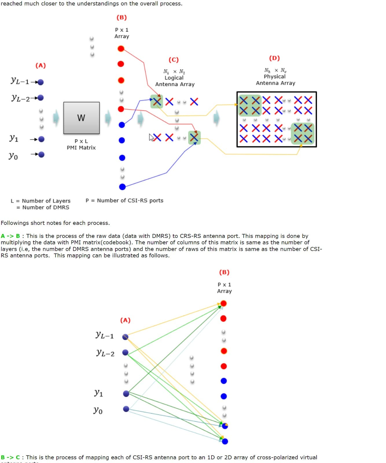
So situation goes like thsi: PDSCH layer 1 data is transmitted to 32 csi0rs ports with 32 different phase shifting
Those 32 signals transmitted from 32 antenna ports will tarvel over the air
And at oen antenna point it will sum up ie all 32 signals will reach taht ue rx antenna with maximum
While for other UE RX antenna will not sum up
This is explained in this picture:
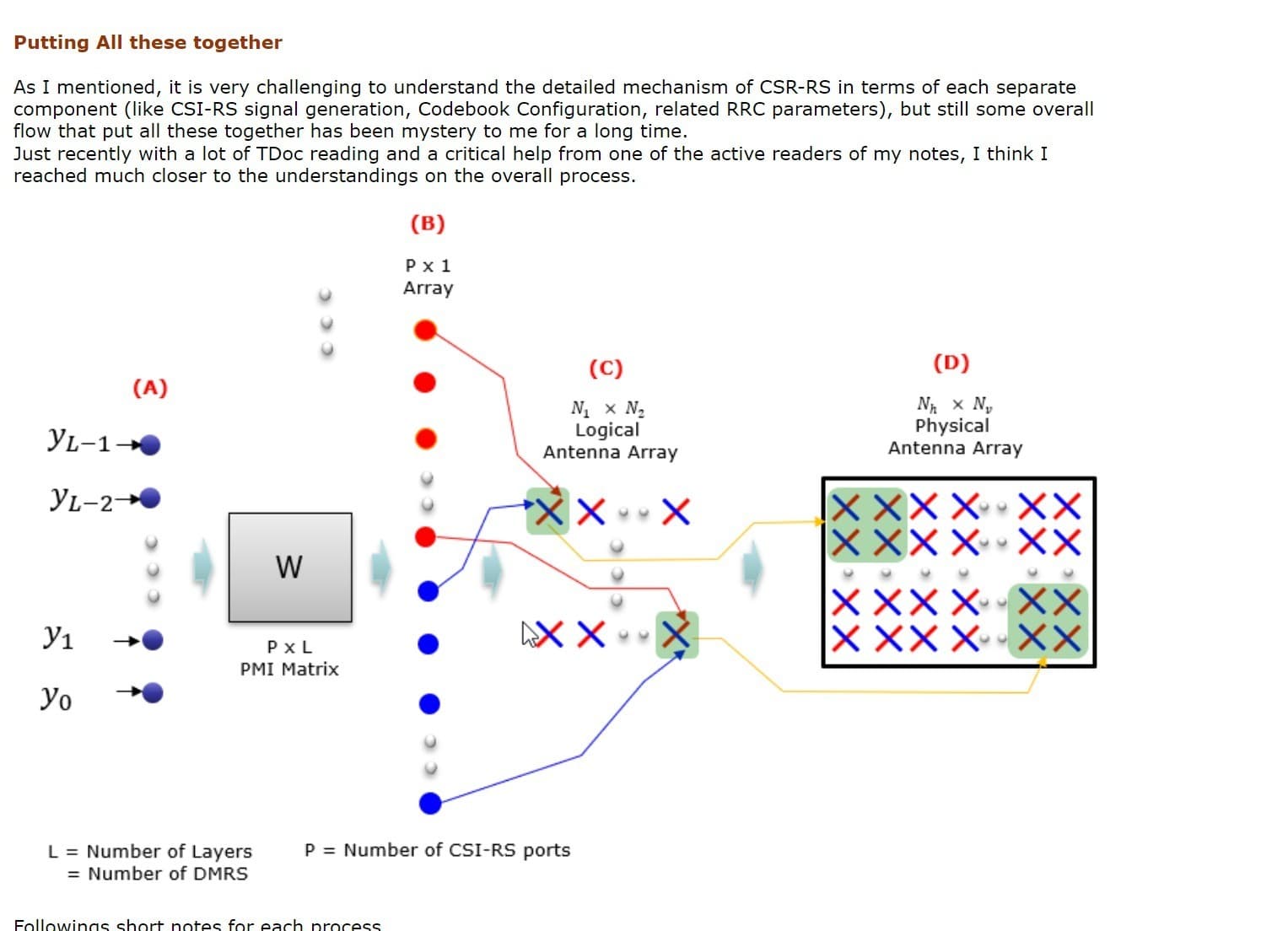
That layer PDSCH1 noted with yo will be transmitted by P csi0rs ports each with a different phase shift.
But in the picture it is missing the UE RX side. It’s just transmission part that is noted in the picture.
Most important pictures from Sharetechnote:
Just read this link several and sevearl times and try to imagine in practice with simple situations and you will understand:
https://www.sharetechnote.com/html/5G/5G_CSI_RS_Codebook.html
Is ZF receiver or LMMSE receiver applicable for both enb & ue side for decoding [Y1, Y2, Y3,…YL] or its applied to enb side only to decode PMI Matrix?
PMI matrix is signaled by UE to NodeB in periodic reports.
Same with rank.
Same with CQI.
Like every 320msec or 160msec or 80 msec.
Depends how it is configured.
Receiver is on UE side to get pdsch data.
Ok so those receiver are present on enb/gnb side looks like.
On 5g those will be carried inside CSI report right.
On eNodeB is just transmitting antenna ports.
C and D in Sharetechnote picture.
It takes a lot of time to understand Sharetechnote pictures but you have to do it one step a time.
Just ask first what you do not understand.
Actually from that snap I am trying to understand how to form the pmi matrix, or what are questions of y1 , y2, y3 …yl for pmi matrix.
1 Like
The discussion we are having is based on beams understanding that is GOB architecture.
Advanced gnb can implement ZF, MRT based precoding that is much different then a GOB based architecture.
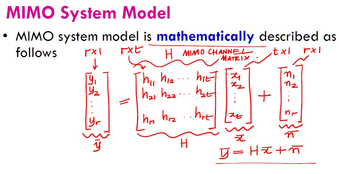
In the picture the matrix is not pmi matrix.
It is the air interface matrix.
This is best idea…lecture will help to understand detailed concept.
This is fading channel matrix, not pmi matrix.
The H factor you see here is actually the Hertian of the channel, X factor is data, n factor is noise
By the way, here its the math model for the wireless system, but you know its not exactly as what’s going on the system in real environment but we can say this is the best math model that describe the channel.
H is fading channel coefficient, for real Matrix hermitial of H & transpose of H is same.
Yes I know it, will check on PMI Matrix later.
No, the response of H depends on which environment you work, impulse transformation for control systems depend on which channel you work with like wireless/cellular/…etc
Yes.
We need H^H (harmitain) actually to calculate main input signal x from different receivers (Y bar).
That’s why you demand that hermitian to be independent.
Can anyone with Huawei experience to spotlight this point?
As I didn’t see any practical implementation for it and wondering if it practically done or not?
If 7+1 beam sweeping is used, only 7 narrow beams are used in sweeping, I mean the horizontal plane one (1 to 7 beams), beam 0 is vertical plane and it’s wide. meanly beam 0 is used to cover the gaps of narrow beams.
1 Like
Thanks @Khader for your valuable input 
This is quite interesting, so in DT measurement, I can see only 7 beams not 8 beams, right? Also, what about the time domain mapping of beam 0 in the vertical domain, is it 4 symbols also? Or something else and where are they located in reference to the other 7 beams? Here, I am assuming 1 beam means 1 SSB block.
Also, is this configuration applicable to all the coverage scenarios?
We can see all SSBs in DT from 0 to 7 (8 beams in total), as I said SSB “0” will be used to cover the gaps of other narrow beams, it’s allocated as usual in slot 0 with 4 symbols starting from 5th symbol (5th to 8th), and used only in default scenario where we have H105 degree and V6 degree.
So in other scenarios it (SSB 0) will be narrow beam as the rest of beams.
Thanks a lot
This info made it more clear to me 
So, if default coverage scenario is used and 8 SSB beams are configured, then by default 7+1 configuration will be applied, right? Or are there more configuration parameters?
Also, what is the target of such a configuration as simply feature like broadcast beam densification can fill the junction between beams when no more than 6 beams are used?