Let me start saying thanks to Leonardo Pedrini for the privilege of writing this series of articles for TelecomHall. He doesn’t do this frequently that I know of. If you like the articles and want to read more then go visit my blog: Smolka et Catervarii (portuguese-only content for the moment).
I’d better warn you right now that you’ll find my writing style quite different from Leonardo’s. While he emphasizes simplicity I’m a bit more fond of rigorousness. So I’ll make a sincere effort to keep closer to his style than of mine. But there will be some rough spots along the way, and I expect this won’t discourage you.
Very well… You probably always heard that telecom networks are based on the circuit switching paradigm. And that was correct up to about 15 years ago. Then started a movement to change networks to the packet switching paradigm. This has been a long, long way, which will be practically complete with 4G mobile networks deployment. Our first step is to understand why this paradigm change was deemed necessary.
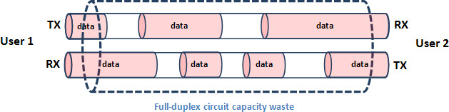
Circuit switching means that the communication channels between user pairs are rigidly allocated for all the communication session duration. Although there’s statistical formulae for circuit switching networks capacity planning – see this Wikipedia article about the Erlang traffic unit – there’s a capacity waste everytime any of the parties isn’t using their communication channel (which is full-duplex, usually).
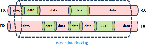
On the other hand, packet switching doesn’t allocate full-session circuits. Transmission capacity in either direction is granted to users just for the time needed to forward a single data packet. This packet interleaving allows minimum capacity wasting of transmission media.
Unfortunately there’s no such thing as a free lunch. Packet switching adoption has it’s trade-offs. The major one is accepting the possibility of congestion, because any network node can suddenly have more packets to send through an interface than it’s transmission capacity allows. Usually that’s dealt with using transmission buffers, so we’re in the realm of queuing systems statistics Erlang C instead of the more familiar blocking systems statistics Erlang B.
Erlang B:
Erlang C:
This and a few other details were the basis for wrong notions about the unfeasibility of carrier-class telecom services – particularly telephony – over packet switching networks. And, with these articles I expect to bury them at last.
Next basic question to answer is: why IP and not any other packet switching network architecture? Why not full-fledged OSI, for instance? The answer is quite simple: other network architectures were considered and discarded because their adoption would be too difficult, or too expensive. The Internet Protocol Suite, on the other hand, was immediately available and was reliable, cheap and simple. With the Internet boom of the 1990’s the option for IP became unquestionable – and quite irreversible.
OSI:
Internet Protocol Suite:
Here in TelecomHall there’s a brief explanation of the 7-layer OSI Reference Model. Likewise, the IP network architecture is structured on 4 layers which match all the functionalities of the OSI-RM layers. Look at the diagram below.
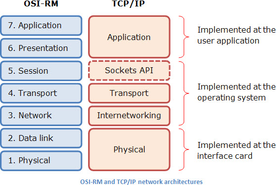
First thing you’ll probably say is: wait a minute! You’ve said four layers, and this diagram shows five. Why so? The answer is quite simple: the sockets API isn’t a real layer – that’s why it’s shown in a dotted box. When TCP/IP architecture was first deployed there’d been need of something to keep different user sessions properly separated. Sockets API was devised to that effect, and became a de facto standard, and was ported to all kinds of operating systems.
Talking of operating systems, one of the great advantages of the TCP/IP network architecture is the simple scheme of work division among hardware (network interface card) and software (operating system and user application). It’s easy, it’s simple, and above all, it works.
On the next articles of this series I will talk with you about the working principles and the main protocols used, with a focus on the use of all this to build the so-called Next-Generation Networks (NGNs). Unlike the usual explanations that you can find about this, I won’t take a bottom-up approach, but will make a top-down description of this environment.
See ‘ya later. Hope we’ll have fun together on this journey.