Introduction
At first glance, this is a subject that seems to be not so important, or at least not have much relationship with Telecom and IT.
But then answer the following question: “If your boss asks you to do a draft, an outline of the installation of a site on the rooftop of a building, how would you get it? What are the minimum information that such a design should contain?”
So, even if it seems a simple matter, it’s worth talking a little about it. Even if only to remind ourselves and meet some basic recommendations for its preparation - remembering that this is an issue with little specific information available.
Objective
Present supporting information for the preparation of a sketch or croqui (croquis - French word that means sketch or draft).
Hereafter, we’ll call this feature a sketch. That’s because we have many ways of naming it, such as Engineering Outline, Engineering Drafting, Technical Draft, Project Draft, etc …
Then: sketch characterized as a drawing, a record of an idea or initial assessment, so that later can progress to the Project.

What is the sketch?
This type of representation is used in virtually all specialties in engineering, and even in areas other than Telecom and IT.
All professionals, regardless of their area, should know and communicate your ideas. And one way to do this is through sketches, through which he can express all its goals.
For example in civil engineering, at the project of a house: first we draw a sketch to define some basic lines as the main rooms, giving ideas of size, measures, among others. Then we proceed to the details of these measures, area analysis, necessary cuts, balconies, etc… Finally, the sketch will evolve into a Project.
This feature is used by Telecom and IT professionals to present their initial project ideas to everyone involved. For this reason, we must follow some good recommendations, making this tool more standardized and professional.
But what if I do not have artistic skills to draw?
We’re not talking about art here, remember that. The point is to present information that might help identify the needs of the project and it’s potential problems.

You only need to know all the details and assess existing information in order to assist the development of the Project.
After the sketches, we follow to technical drawing. An yes, it should contain more accurate and detailed information - which leads to more time spent in their preparation. The technical drawings already represent the final and definitive Project, which was discussed from the sketch.
A practice sketch professional can easily take any scenario to be discussed by the team involved! If you practice, you can do it too!
And what it takes to make the sketch?
A pencil, an eraser, a piece of paper … and your imagination!
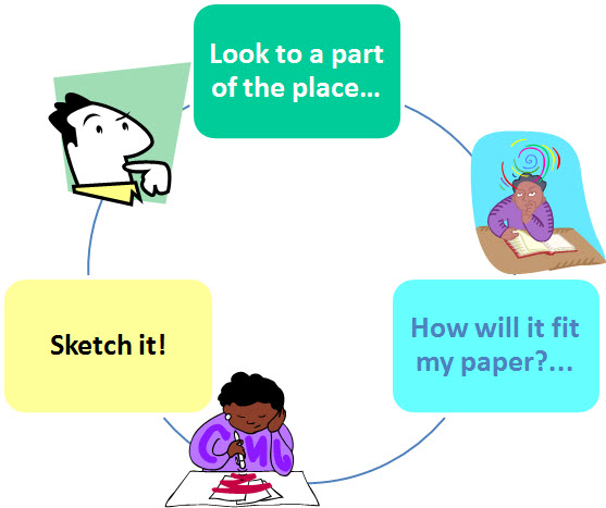
-> First , look at where you want to portray. Then view as a part of it would fit into place in your paper. And Draw!
Done! You’ve learned the ‘technique’ to draw any sketch.
It might seem fun, but that’s it. It will only depend on the practice, and repeating the steps. For this go by drawing parts - look at the site, visualize in your mind how each part will be the drawn … and draw it!
It is more or less like a loop, as shown in the following figure.
Just one final tip: make a first draft containing all the edges or outer limits of the area involved. So you can be sure that you can draw smaller areas - contained within the boundaries - without the risk of paper end up being small!
Telecom and IT Sketches
In the area of ??IT and Telecom have some specific types of sketches.
A specific type of sketch is used to guide the course of arriving at a point not well known, for example for a new station on a hill. This sketch is known as Access Sketch and is done with the help of GPS - and now also with the help of geo-referenced tools like Google Earth.
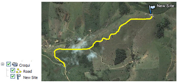
Another important type is the Situation Sketch or Installation Sketch, which in the case of Telecom, is very common. This document is very important - perhaps even essential - to streamline projects, assisting the decision-making.
It is up to the designer to draw the sketch in a fast, simple and didactic, seeking to register the most relevant information, according to the purpose for which will be used to this.
There are rules for drawing up the sketch?
No, only recommendations. As we mentioned earlier, the first action is to seek to know the purpose for which the document will be used. Knowing the components of the system will be installed, with emphasis on space.
And as we always do to try to better illustrate, let’s imagine a WiMax system to be installed on the roof top of a building.
A typical project will be basically composed of:
- A processing station (BTS / Node);
- One or more antennas;
- Cables, Connectors and similar /auxiliar equipments;
- Supports;
- Power and Grounding;
- Link Connection Control (TX).
The first thing to do - naturally - is to go to the place appointed for the installation of equipment.
Current and Proposed Layter (optional)
Some professionals likes to work with two sketches: one with the current situation, and one with the future situation (the proposal). (Although the most important is the sketch to the final position).
In this case, starts drawing up the sketch of current area of the site - Current Layout sketch.
Then, from the current sketch, the proposed changes are drawn - Proposed Layout.
General Recommendations
We have said that there is no rules to be followed, but some guidelines may help. So here we go …
Identify the location for installation of fixed unit processor. This includes defining the space with measurements of the site as a whole, and the space that the equipment will occupy. Should be made a critical analysis considering height, clearance required, ventilation conditions, etc…
It is also important to check how the move will be made for installation and maintenance.
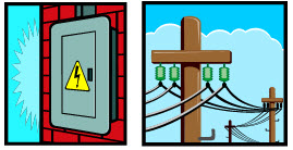
Identify the source of supply for equipment, and also the location for grounding point. Also, inform the nearest point of connection with the energy supplier.
Identify the location for Antenna(s) installation(s) observing the point of irradiation and the method of fixing it. In some cases it is advisable to make a vertical cut to better detail the position(s) of the same(s).
Indicate in the sketches the referrals of all cables, be it power, antenna (s) interconnection(s) or grounded.
Regarding the scales used, the sketches are not necessarily drawn to scale (although this is of course possible). Only indicates the key measures relevant to the project. Remember that we are dealing with a sketch, not the final project.
The Magnetic North should also be indicated in the drawing, and is also good to inform the streets near the site.
Another tip would be to highlight the existing area (m2) approximately, and the area intended for use for the project, which are all components of the system.
The sketch should show text identifiers of system components (green area, balcony, etc. …). It is also common to use hatch, to distinguish different areas. Finally, also it is recommended to inform the dimension, ie the heights of the most relevant areas around the site.
Control Information
To finish, the sketch should contain some basic information control.
- Description : usually the name ‘Engineering Sketch’ followed by the name of the site;
- Date : the sketch was made;
- Review : for cases where you need a new sketch;
- Author : containing the name of the sketch’s performer or designer;
- Location : containing the address.

Examples of Sketches
Finally, here are some examples of sketches.
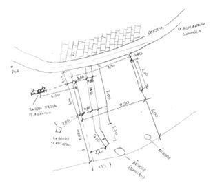
The sketches can be made freehand on a blank sheet.
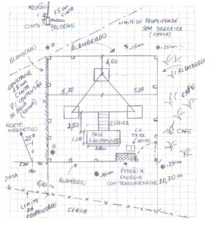
And can be made into sheets with checkered background, facilitating the design.
Important : In all cases, it is recommended that the sketch is then scanned, or converted into digital document.
Thus, the sketches can be sent to the team responsible for preparing the Technical Design using professional design tools like AutoCad.
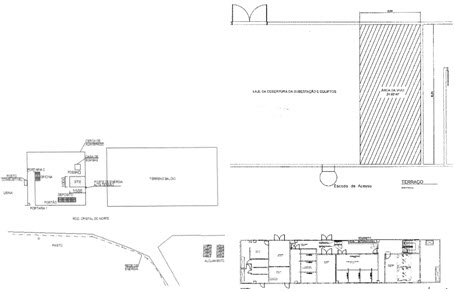
You can download a very simple example of a sketch template in the Download section of this tutorial.
But remember: just a sheet of blank paper, a pencil, an eraser … and practice!
Conclusion
Today we present a brief suggestion or guidelines to follow in preparing a sketch - the first draft or outline of a Project.
A good outline should contain information allowing the best possible representation of the situation of where the project will be conducted. The better the sketch, the better the chances for a good Final Project.
Download
Download Source Code: NA