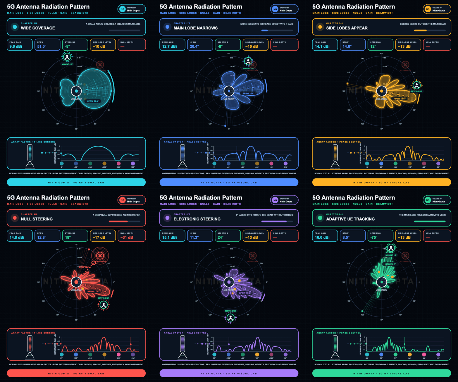
This animation explains the key concepts behind a 5G antenna radiation pattern.
MAIN LOBE
The main lobe represents the direction in which the antenna transmits the strongest radio energy.
BEAMWIDTH
Half-Power Beamwidth, or HPBW, describes the angular width of the main lobe between its −3 dB points.⠀
A broader beam covers a wider area. A narrower beam provides greater directivity and concentrates energy toward a selected user.
SIDE LOBES
Not all energy remains inside the main beam. Smaller side lobes appear in other directions and can contribute to interference.
⠀
NULL STEERING
An antenna array can create a deep reduction in gain toward an interference source. This is known as null steering.
⠀
ELECTRONIC BEAM STEERING
By adjusting the relative phase and amplitude applied to individual antenna elements, the network can change the beam direction without physically rotating the antenna.
⠀
ADAPTIVE USER TRACKING
As the user moves, the network updates its beam configuration to maintain signal quality and reduce unnecessary radiation in other directions.
⠀
The animation also shows:
⠀
• Peak antenna gain
• Half-Power Beamwidth
• Steering angle
• Side-lobe level
• Null depth
• Array-factor response
• Phase changes across antenna elements
⠀
The radiation patterns are illustrative. Real antenna behaviour depends on element design, spacing, frequency, array geometry, weighting, propagation conditions and the surrounding environment.
⠀
Which RF concept should I visualize next?
LinkedIn: 