Introduction
In an LTE (Long Term Evolution) network, the term “gain” refers to different power adjustments applied to various components of the data transmission and reception system, such as antennas, cells, and signaling channels. These adjustments are fundamental to ensure that signals are transmitted with the correct power, optimizing coverage, signal quality, and network performance. The gain directly influences the coverage of a cell, the ability to serve users, and the efficiency of frequency spectrum use.
In this article, we will explore how the gain of an LTE site can be checked, using the “hget . gain” command, applied in an Ericsson network. We will also analyze a real example of the output of this command, detailing what is checked and offering a technical opinion on the parameters presented.
“hget . gain” Command
The “hget . gain” command is used in Ericsson networks to inspect various parameters related to the gain of an LTE site. This command can provide detailed information on the following aspects:
-
CRS (Common Reference Signal) Gain: Related to the power of reference signals.
-
PDSCH (Physical Downlink Shared Channel) Gain: Refers to the power applied to the channel that carries user data.
-
Antenna Gain (iuantAntennaOperatingGain): Indicator of antenna performance.
-
NB-IoT cell gain: Specific for NB-IoT networks that operate in conjunction with LTE.
Detailed Analysis of Command Output
Below, we will detail the parameters displayed in the command output example:
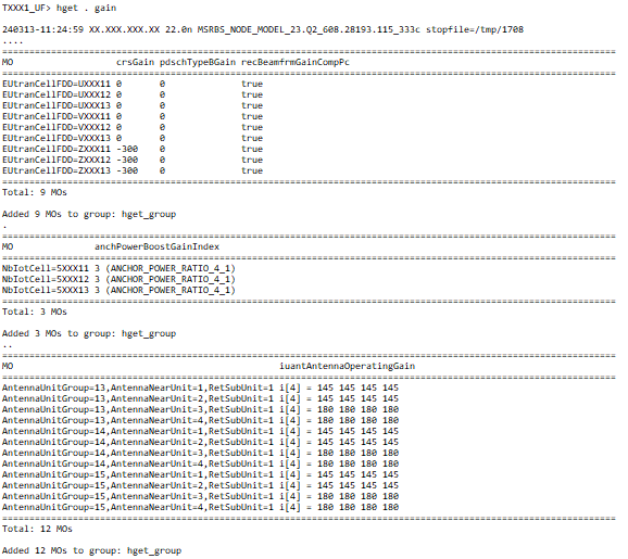
- crsGain, pdschTypeBGain, recBeamfrmGainCompPc
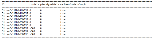
In this section, we can check the following parameters:
- crsGain: It is the gain of the common reference signal (CRS). Here, most cells have a gain value of 0, that is, without additional gain. However, cells ZXXX11, ZXXX12, and ZXXX13 have a negative gain of -300, which may indicate a significant reduction in CRS power, potentially affecting coverage in these cells.
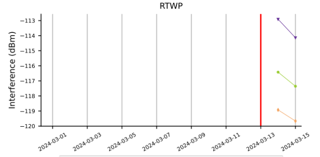
In the case of 700 MHz cells, which have a lower frequency range and therefore greater coverage range, a reduced CRS gain (like the negative values of -300) could be intentional to control the RTWP < -108dBm, because:
By reducing the crsGain (Reference Signal Gain), the effective range of the cell is reduced, limiting the downlink coverage area.
A more restricted coverage can result in fewer users connected to the cell, reducing traffic and interference on the uplink.
As a consequence, the RTWP can be kept at acceptable levels, avoiding overload of interference and improving the overall quality of the signal received on the uplink.
-
pdschTypeBGain: It is the gain applied to the PDSCH channel, responsible for transmitting user data. All cells in the example are with the value 0, suggesting that no additional gain was applied to the PDSCH.
-
recBeamfrmGainCompPc: This parameter indicates whether the beamforming compensation gain is active. The true value shows that this functionality is enabled in all cells.
- anchPowerBoostGainIndex
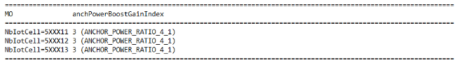
In this section, we observe the gain index of the NB-IoT cells:
- anchPowerBoostGainIndex: Refers to the power gain index of the NB-IoT anchor channel. The value 3 indicates that the NB-IoT cells are configured with a 4:1 power ratio between the anchor channel and the other channels, which seems appropriate to ensure good coverage for NB-IoT devices.
- iuantAntennaOperatingGain
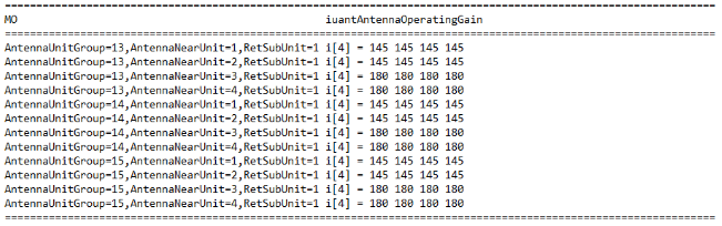
Here, we observe the operational gain of the antennas:
- iuantAntennaOperatingGain: Shows the gain applied to the antennas. The values are expressed in 145 and 180, which may represent good gain performance, with balanced sectors. This suggests that the antennas are operating with good transmission efficiency.
TXXX1_UF> hget . gain
Technical Opinion on the Example
Based on the analysis of the data presented, the gain of the cells and antennas at the demonstrated LTE site seems, in general, to be within acceptable limits for most parameters. However, the negative values of crsGain for cells ZXXX11, ZXXX12, and ZXXX13 (-300) are a cause for attention, but as we saw earlier they have a justification, since these values indicate a possible attenuation of the common reference signal, which can negatively impact coverage and in return keeps RTWP levels within the acceptable target.
The antenna gains, on the other hand, seem appropriate, with consistent values between the different sectors (145 and 180), which suggests a good configuration to ensure signal propagation.
Regarding NB-IoT, the gain index is adequate to support the operation of IoT cells with a balanced power ratio between the channels.
Conclusion
The “hget . gain” command is an essential tool in Ericsson networks to monitor the gain at an LTE site, ensuring that signals are transmitted with the correct power to maximize coverage and network performance.
The optimization of gain is a critical factor for the success of an LTE network, and fine adjustments can ensure better quality of service and a more satisfying experience for end users.
LinkedIn (in Portuguese): ![]()