Difference between CSI-RS and TRS configurating under Non Zero Power IE

Hi Experts ,

I’m not able to understand difference between configurating CSI - RS and TRS under Non zero power IE

I need to configure CSI-RS on symbol 6 and TRS in symbol 7

//For CSI-RS
NZP-CSI-RS-Resource
nzp-CSI-RS-Resourceid:1
resourcingMapping
FrequencyDomainAllocation : row1
firstOFDMSymbolinTimeDomain:6
density:1

//For TRS
NZP-CSI-RS-Resource
nzp-CSI-RS-Resourceid:1
resourcingMapping
FrequencyDomainAllocation : row4
firstOFDMSymbolinTimeDomain:7
density:3

Here only density,firstOFDM symbol and frequecy domain allocation is there

But how UE will know which is TRS and which is CSI-RS

Because i can configure vice versa as well
like

//For TRS
NZP-CSI-RS-Resource
nzp-CSI-RS-Resourceid:1
resourcingMapping
FrequencyDomainAllocation : row1
firstOFDMSymbolinTimeDomain:6
density:1

//For CSI - RS
NZP-CSI-RS-Resource
nzp-CSI-RS-Resourceid:1
resourcingMapping
FrequencyDomainAllocation : row4
firstOFDMSymbolinTimeDomain:7
density:3

Can anyone help me understanding how to configure this two Reference signals

For TRS, all the 4 NZP-CSI-RS-Resource (each with density 3) are grouped in a NZP-CSI-RS-ResourceSet with trs-info = true

Why group of 4?

TRS pattern is defined in:
Freq domain: 3/ RB ( density 3)
Time domain: 2/ slot for 2 consecutive slots ( 4 NZP-CSI-RS-Resource) then repeat periodically

Yes understood for TRS

What about CSI RS with density 1
Do i need to configure in same way

i mean in group OR i can configure in single NZP-CSI-RS-Resource

Also how can i give delay of 1 slot ?

This is for DSS and MBSFN configured on SUBFRAME 1

So without delay if i configure NR reference signal would occupy in SUBFRAME 0

i can see there is IE periodicityAnd Offset : Slots20 // Here i could see only periodicty is being configured

but where to configure offset?

For CSI RS, you can configure one resource but I think it has to be put in a group as well
For offset it should be after the periodicity for example Slots20:2 for offset 2 slots

Yes i configured accordingly

Now i’m facing difficult placing SSB position

How do i calculate SSB start indices for a given band

For example i’m using n28 FDD

So from table

table 1
Understanding NR5G Synchronisation Signal Block (SSB) | by Prateek Mishra | Medium

I can see
Case A
Case B
Case C

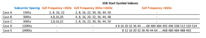
Initially i had used 15khz SCS and there was only one entry and i concluded from the table that start position was 2,8,16,22

But now i’m configuring Non MBSFN based DSS which leaves me to use 30khz sub carrier spacing SSB so that i can transmit withing 2 symbols (becuase in Non MBSFN based DSS i had maximum 3 continuos symbols without CRS of LTE So cannot go with 15khz SCS for SSB)

And the band i’m testing is n28 which is of FDD

Now i want to know the start indices of the SSB
Which should i consider for FDD case B OR case C from the table?

In simple words how do i classify FDD and TDD bands under different CASE in table

B28 can only use Case A
Refer to Table 5.4.3.3-1 in 3GPP TS 38.101-1 v16.4.0 for cases applicable to each band

Thank you for info