Correct Cabling at a Site

Hello Experts,

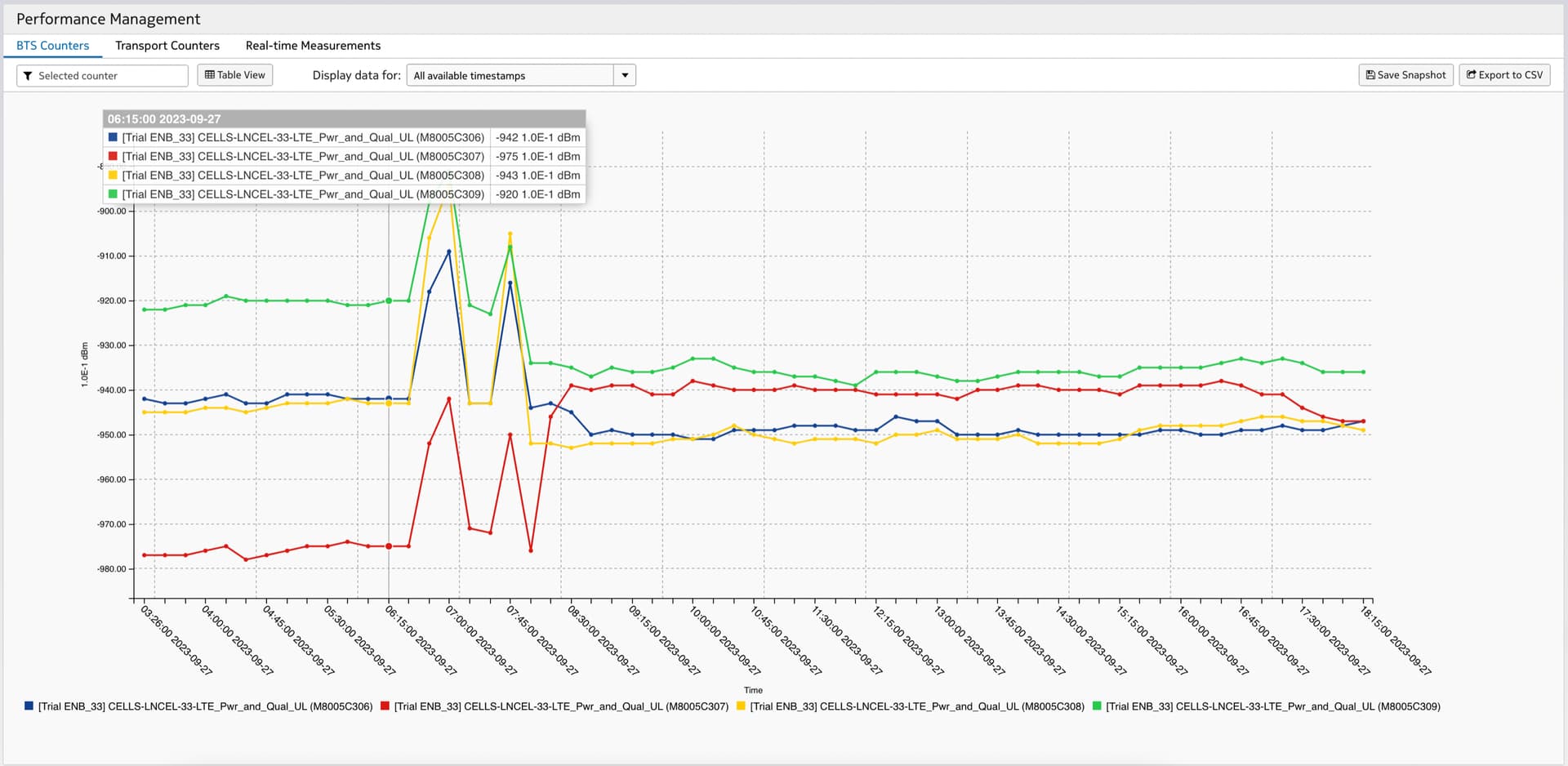
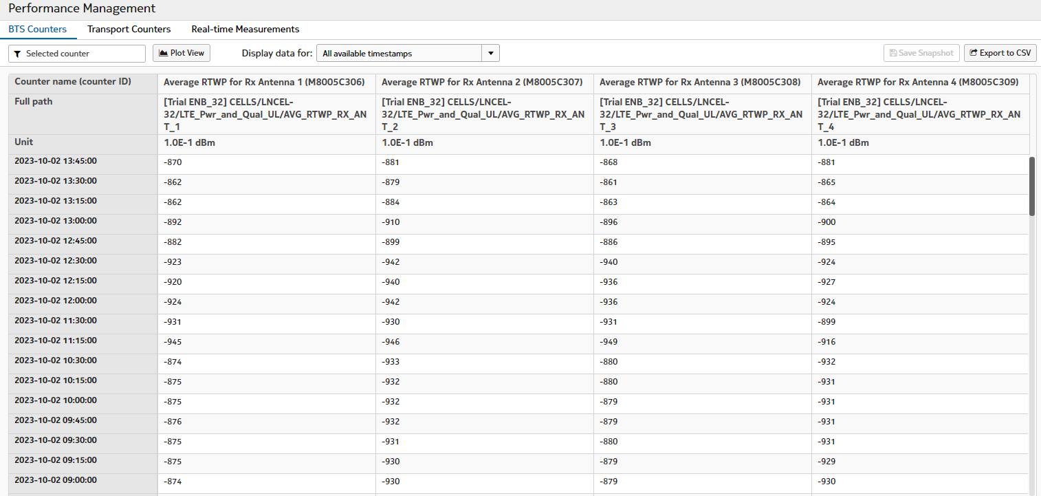
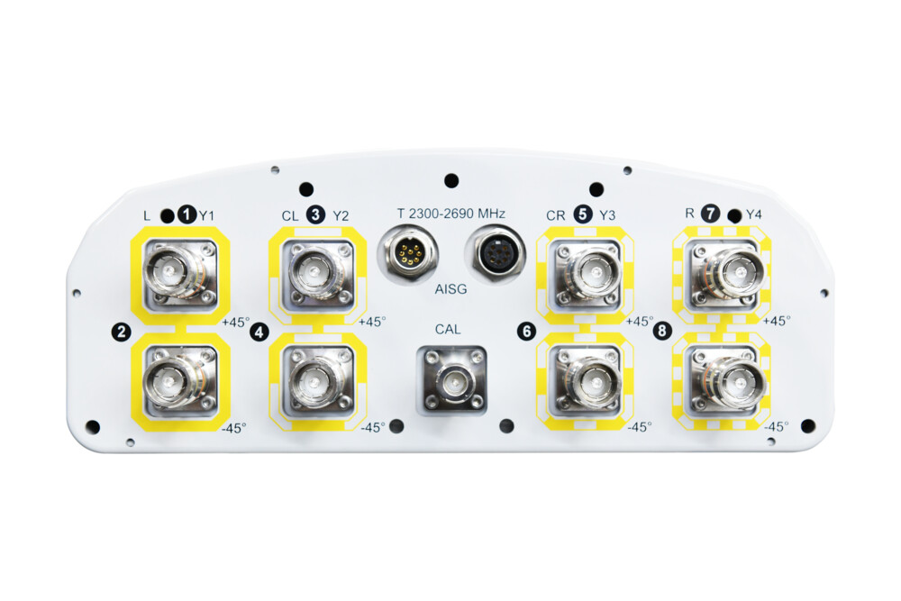
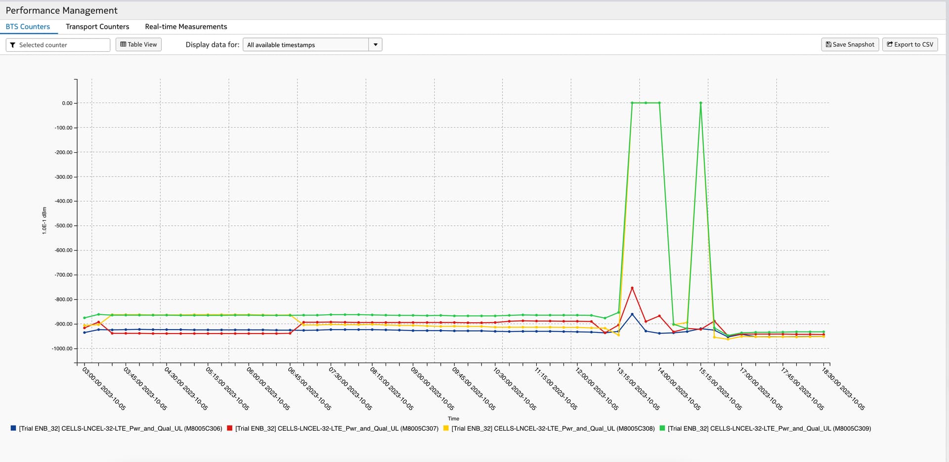
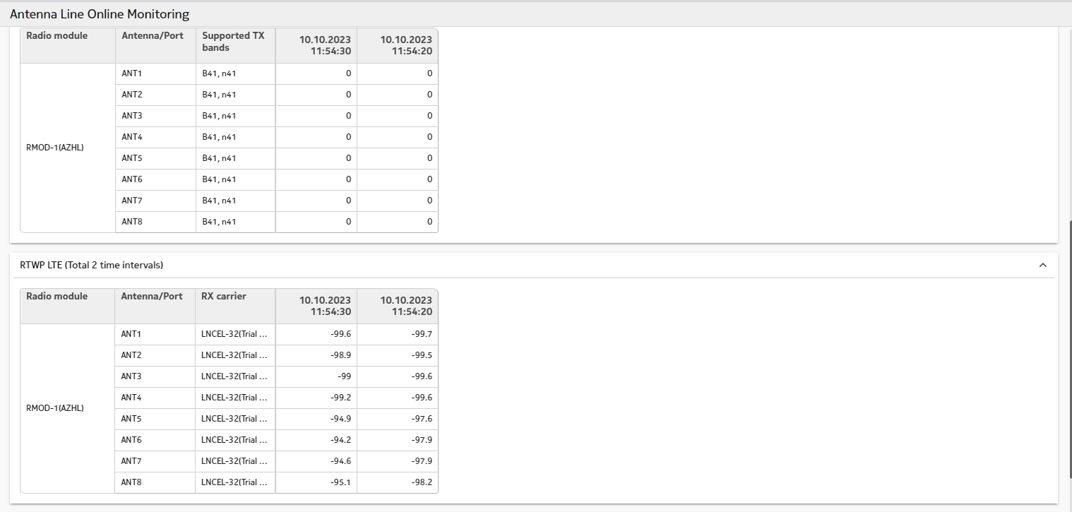
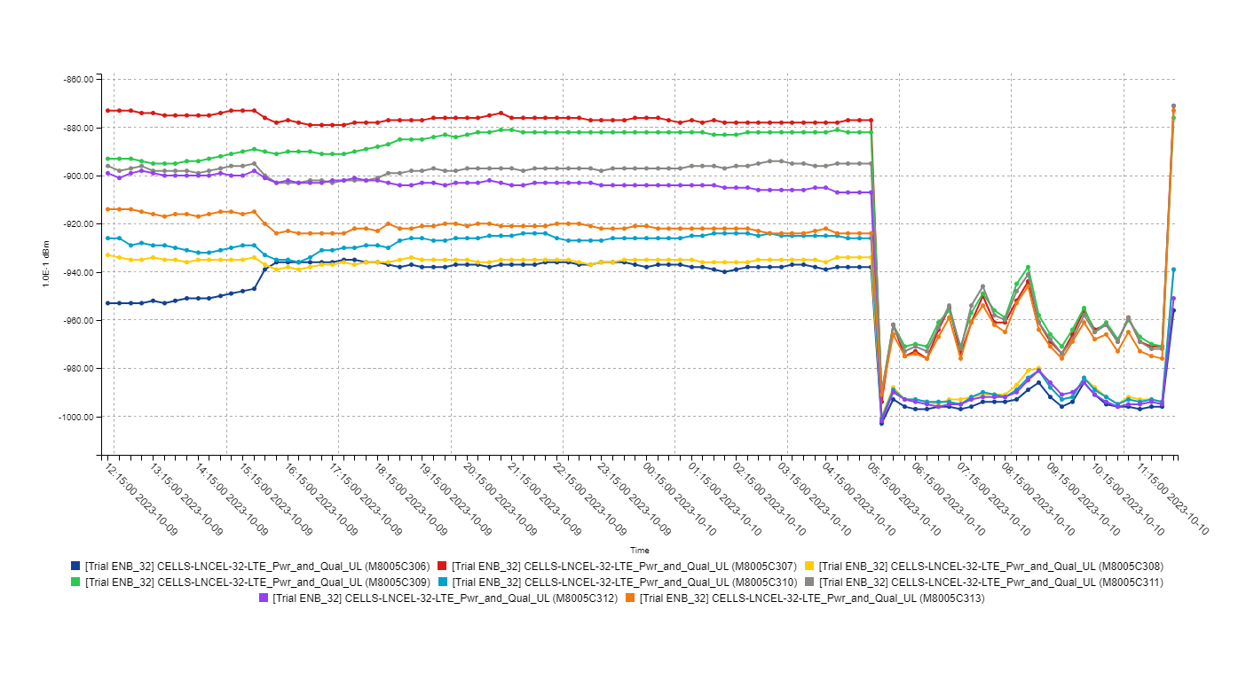
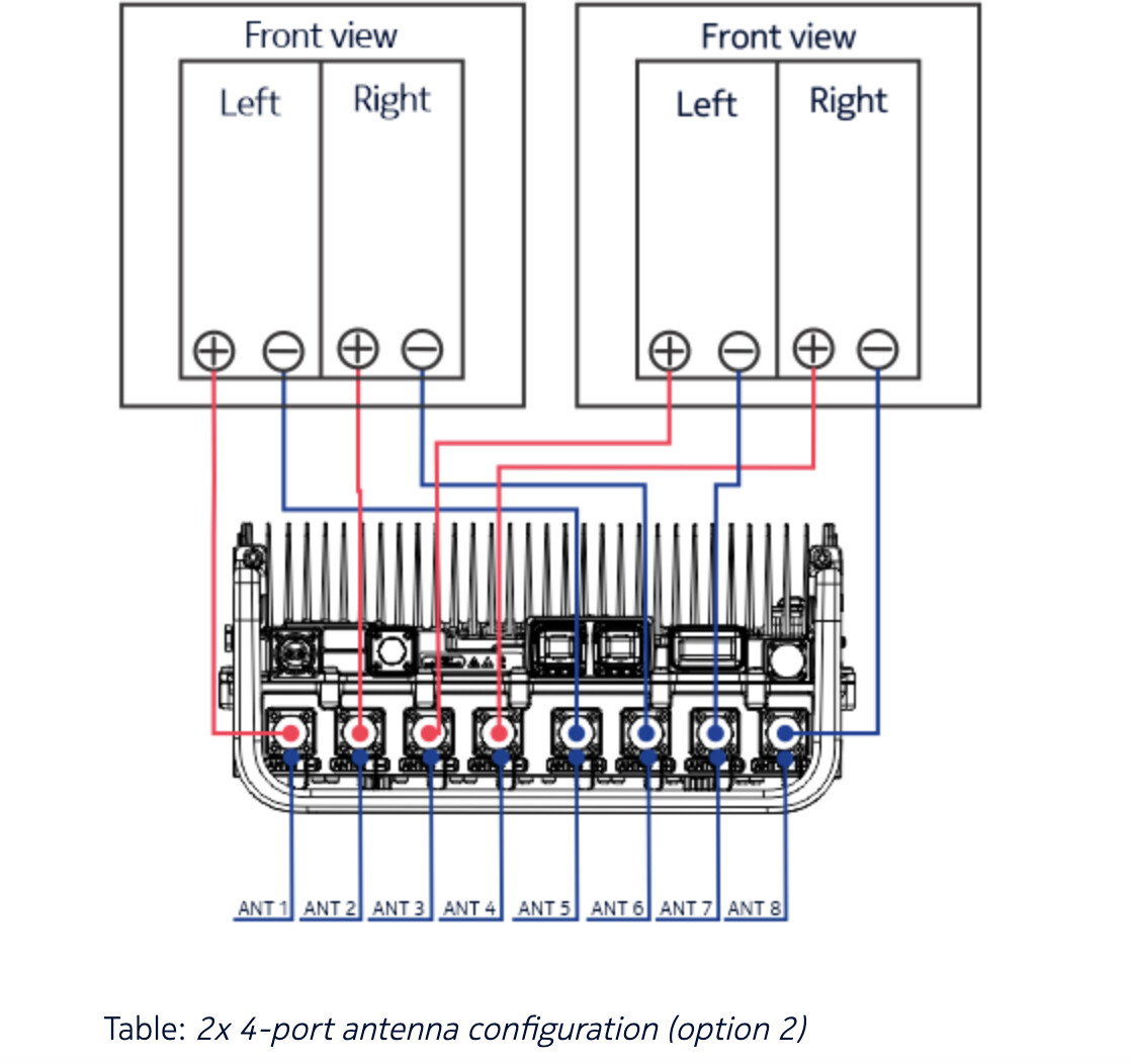
I am relatively new to LTE. I am deploying a small, private FWA network with Airscale AZHL. I am configuring 4x4 and have a question about the cabling. I have had a problem with RTWP imbalance and finally decided to try a new antenna to solve the problem. I thought things were better but they are worse. RTWP is great but there is s significant imbalance in RSSI at the UE. It looks like positive polarization antenna are receiving signal and negative are not, So I check the antenna assignments and yes only the positive antenna are in use. This makes perfect sense because we changed the cabling of the antenna back to recommended in the manual:

So I changed the antenna assignment to match the new cabling of the antenna as denoted in the picture by 0 2 1 3. This caused the 5db RTWP imbalance to return but alleviated the imbalance on the UE side. Performance overall has now dropped back to 100Mbps.
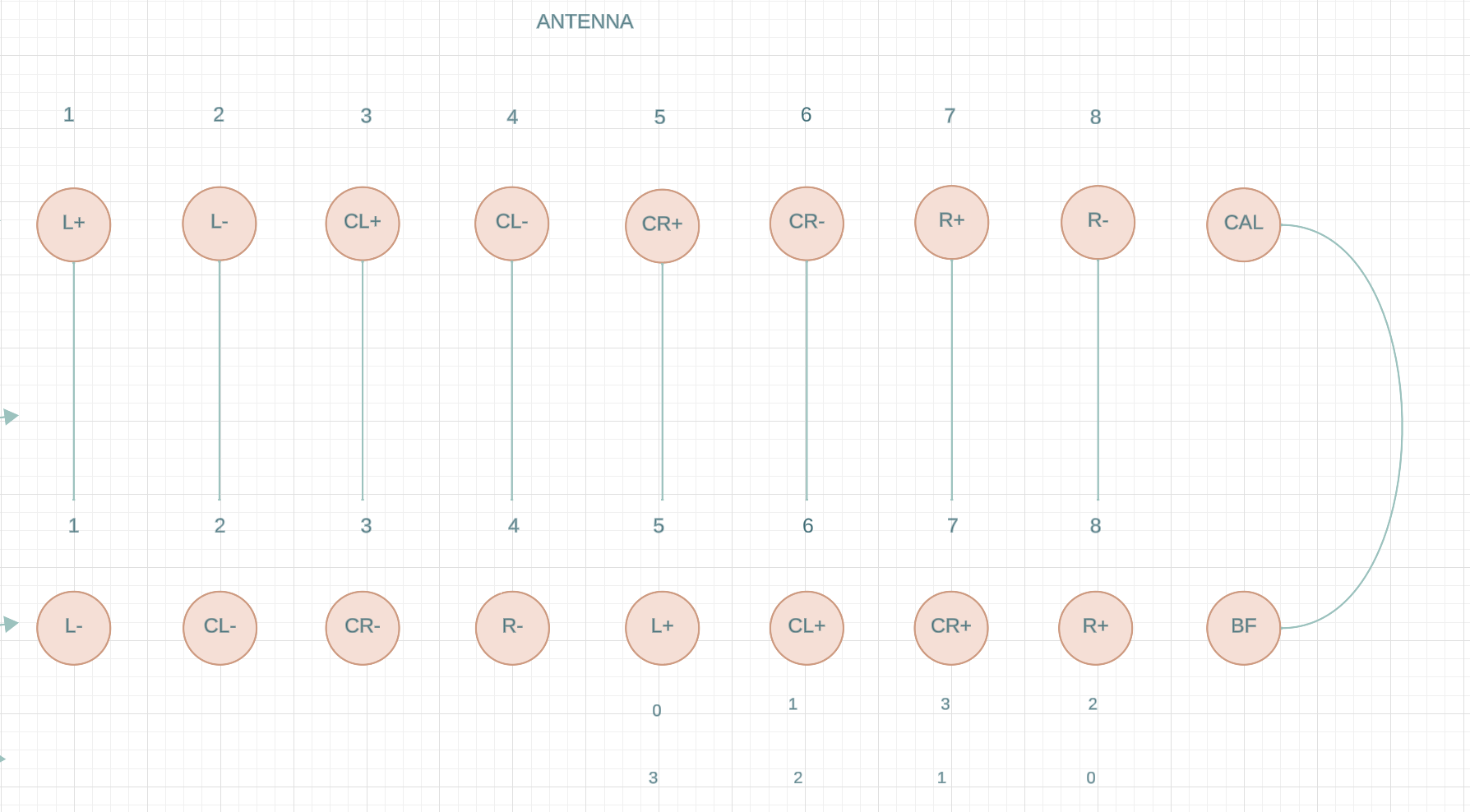
The original 200Mbps + config was based on this wiring:

Which yields much better results even though the Nokia manual recommends the first picture as the appropriate wiring.

However,

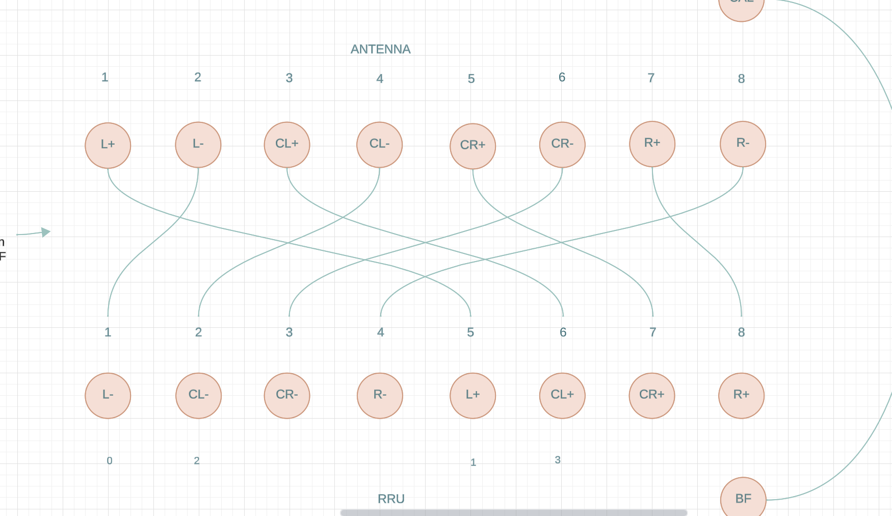
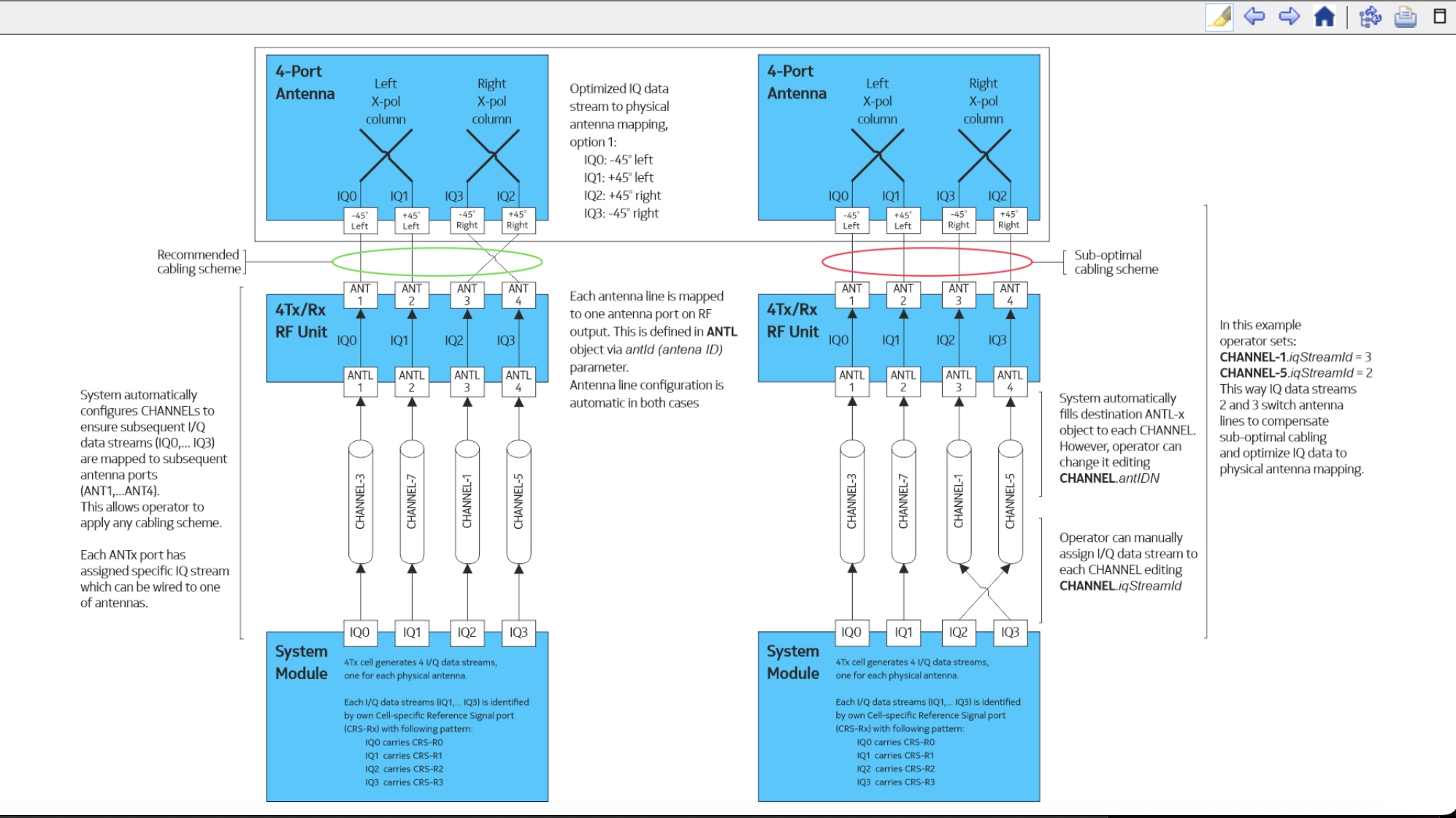
If one reads about software antenna remapping……a different picture is presented:

This image and the possibility of antenna remapping would suggest that the wiring of the antenna ports is truly + - + - + - + -

and not as presented in the equipment documentation

BECAUSE……the IQ stream is polarization aware and the browser states that if antenna port remapping is not activated (which in most cases it is not) that the BTS assigns IQ data streams in sequence + - + - + - + - so sometimes if you’re antenna elements are oriented + - - + then you need to cross 2 cables physically or remap Them.

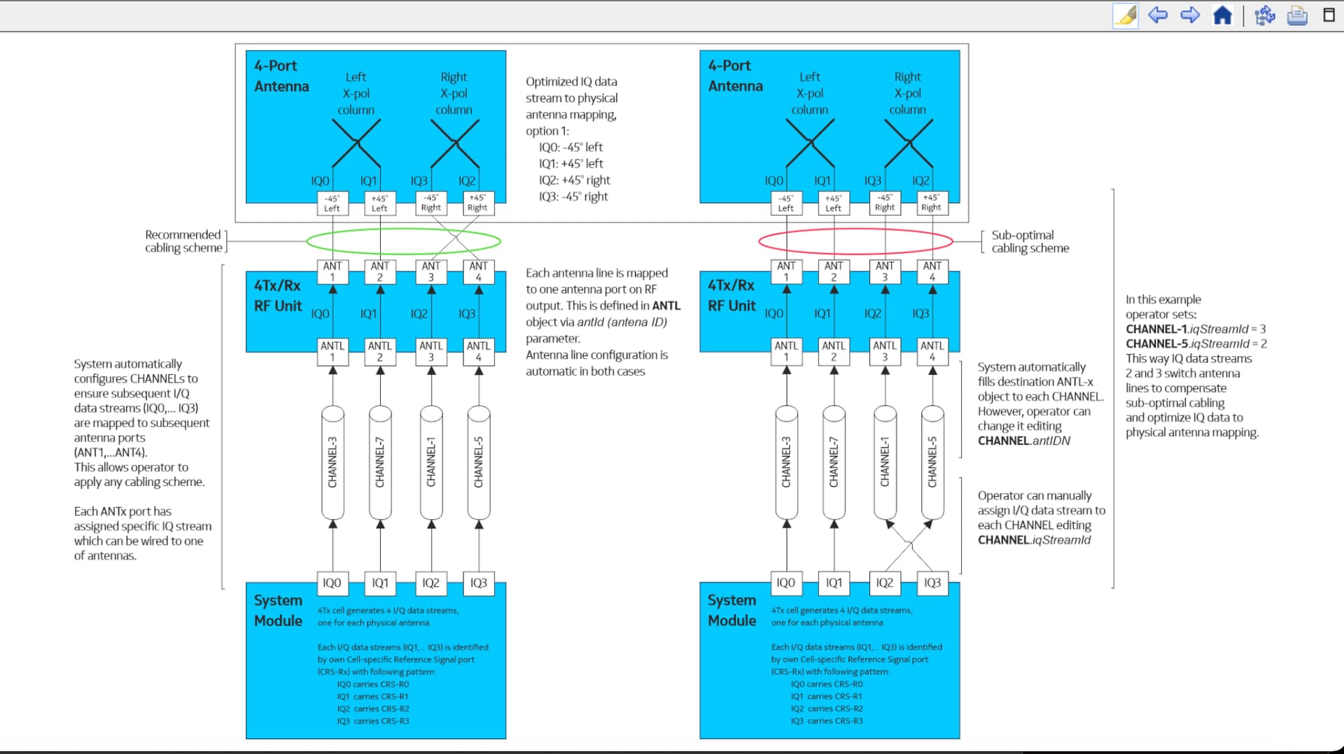
"Before the introduction of LTE3639, or when it is not active in a cell, the system configures CHANNEL objects automatically (for example the Distinguished Name of antenna line (antlDN) and Channel identifier (channelId) parameters), meaning that in the TX direction, consecutive I/Q data streams are mapped automatically to consecutive RF antenna ports in the RF unit. In this way, the operator knows which I/Q data stream is transmitted from each antenna port and can set up the wiring on the actual site.
The LTE3639 feature is activated or deactivated at cell level by using the Activate software antenna port re-mapping (actAntPortMap) parameter.
"

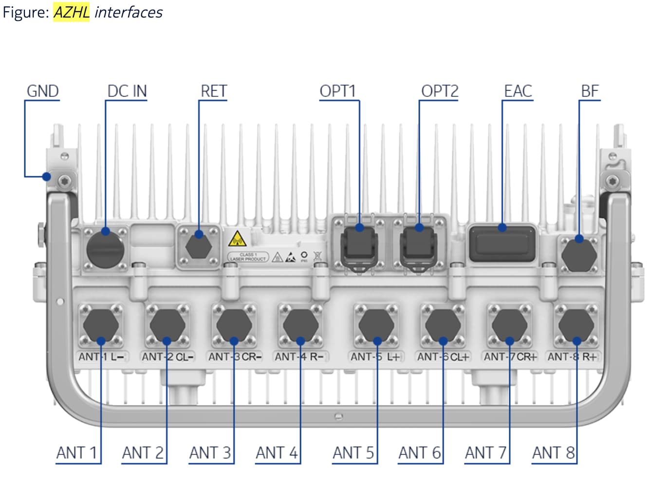
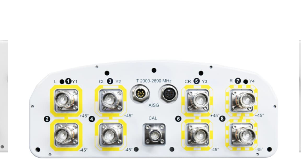
This is counter intuitive to markings on the Radio ports. The ports are all labeled - - - - on ports 1-4 and + + + + on ports 5-8.

This cannot be true if the documentation on antenna port remapping is accurate. If antenna port remapping works like it says it works then the ports go + - + - + - + - + BECAUSE the IQ data stream dictates the polarity of the port.

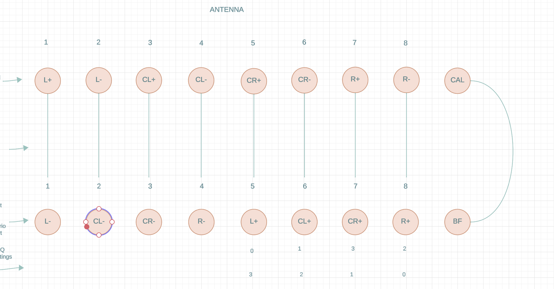
To sum it up in pictures………. this:

Cannot be true at the same time as this:

But I also know that I cannot assume I am right. even though I have seen 100% increase in throughput by wiring the antenna like this:

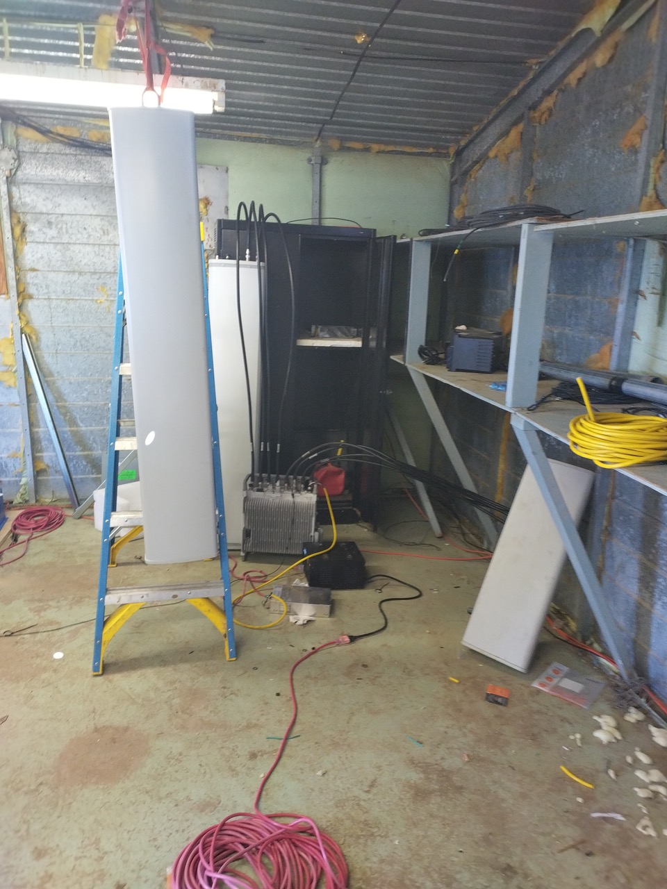
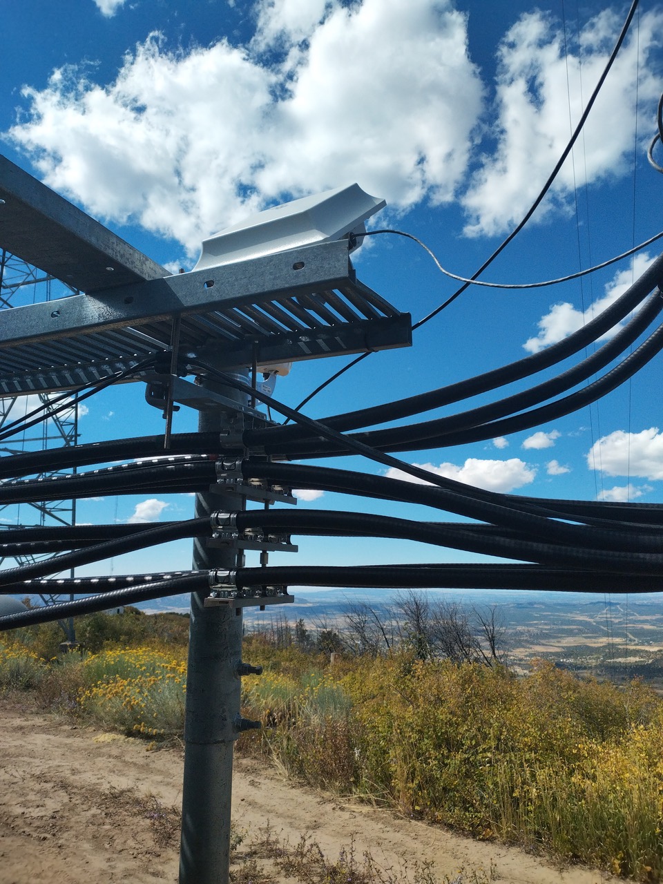
Here is a picture of the bottom of the antenna:

anyone here knows better than me. How the HELL are you supposed to cable this antenna to the AZHL?

Welcome, Michael_Halls! It’s great to have you in our community. If you have any questions, need information, or just want to engage in discussions, feel free to ask. We’re here to help and share knowledge. Enjoy your time here!

I broke this down to a lab and tested several antenna. I found that using a simpler non-beamforming antenna as significant positive impact on RTWP in my system.

In brief:

Downgrade to the most basic of antenna capable of 4x4 yielded the highest throughputs in excess of 220Mbps with 200 delivered to a test UE.

It also yielded almost full correction of RTWP readings but still intermittent VSWR reporting.

The more complex antenna always suffer from 5db imbalance between each pair of antennas with most interference occurring on the + pol elements of the antenna.

I also tested a 3rd antenna which was again very basic but higher quality than the previous basic antenna. This antenna fell somewhere in the middle for RTWP balance.

This was a very thrown together lab at the base of the tower site with the UE outside and the transmitter inside the building about 6-7m away.

I am still unsure of this because well…….anything would perform well with an RSRP of -60

BUT……absolutely the only point of this lab was to compare RTWP. Unfortunately I do not have screen shots of all three but the setup was:

Antenna mounted on the tower currently serving customers

Identical antenna to that in the lab

These 2 antennas showed identical or at least extremely similar RTWP values with a consistent >=5db imbalance between Paris of ports

In the lab there were 2 more antennas

A KP performance basic 4 port antenna with fixed tilt

And a very small Anatel antenna which cost something like $250

This second group of antenna also performed similarly and resolved to a significant degree the RTWP imbalance.

Well…went up to the lab and put all the cables back in correct polarization on the RRU. removed some adapters from the cable ends and straightened the 9 foot cable run and …RTWP got better…its still a bit high but i THINK thats because the RRU is inside a building with the antenna.

Well

Like usual I thought I did some good but not yet. After moving all the cables back to Polarized positions I realized that I am now using only negative polarity elements to TX which is fully counterintuitive given that my rtwp is now seemingly OK…?

It occurs to me now that the BTS may be aware of how to organize the polarity of its ports based on mimo mode. I have no evidence to support this other than the above images of antenna port remapping feature but it does seem logical that while in 4x2 or 4x4 mode it would operate as 2 individual 4t4r cells. If that is the case then I can see how according to the antenna port remapping feature the ports are oriented + - + - + - + - . While operating in 8t8r it changes to - - - - + + + + as labeled on the physical RRU ports. so this would require remapping to occur if the antenna is wired according to 8x8 and you wanted to use it as 4x4. In theory…setup a 4x4 cell then use antenna port remapping to adjust polarity to the suggested - + + -.

So we look at the antenna ports:

then the radio ports:

we see that we are aiming for this wiring:

focusing on what ports we might like to use we see that we can use the left side of the antenna by utilizing ports 1,2,5,6.

so 1,2,5,6 become ports 1,2,3,4 in the context of antenna port remapping but should we pause before the remapping and assign channel 1 to port 5 channel 2 to port 1 channel 3 to port 6 and channel 4 to port 2?

Ill edit this in the morning but for now we will use ports in order so 1,2,5,6 are 1,2,3,4

then we look at our port remapping diagrams:

Based on that diagram we are now 1,2,5,6
+,-,+,-
0,1,2,3

so we use antenna port remapping to optimize the polarity pairing by flipping IQ data stream 2 and 3…again in theory. I will update tomorrow after the tests. I will also go through the process of reassigning the channels instead of the IQ data streams essentially not using antenna port remapping but changing the port a channel uses.

No cable swapping or Channel swapping or IQ data stream assignment has helped the RTWP at all. I have now pretty much fully concluded that the T4-90B-R1-V4 antenna requires some further configuration to integrate to the RRU. After reading about the CAL port here: Here

I see that its main job is to compensate for differences in received power and even things out. Well…its not doing that and I am searching for a way to validata and or activate the operation of the BF port on the AZHL RRU.

I achieved good RTWP by changing the antenna to a basic 4 port antenna with fixed tilt and no beamforming specialty. The leftmost of this graph is the Commscope 8 port antenna, the center is the best I could do with RTWP by changing cable positions etc. The rightmost of the graph is finally the change to the 4 port antenna. so fuck TM9 I guess…

I have now seemingly resolved the RTWP imbalance issue. I did this by implementing a beamforming configuration using the T4-90A-R1-V2. I applied specific beamforming weight values as seen in the Nokia information browser when configuring LTE3197. The antenna is supposedly optimized to operate with LTE3917 and lo and behold…when I apply this configuration this is what RTWP looks like for 2 days now:

I am still concerned that I do not see VSWR measurements. There is an explanation for this in the manual that concerns me because it would indicate that I do not have to correct cabling still:

" The average of Voltage Standing Wave Ratio (VSWR). The counter reports the sum of VSWR value samples taken every 1 minute during the measurement period. Transmitted power and reflected power interferes and forms a standing wave. The VSWR is defined as the ratio of maximum to minimum in this wave. VSWR = (transmitted power + reflected power)/ (transmitted power -reflected power). If the VSWR value is unreliable for the whole period, the value is set to 0xFF. An actual measured VSWR value is reported as multiplied with 10. Unreliable conditions are invalid VSWR alarm, TX low power alarm, VSWR minor alarm or VSWR major alarm.

The counter reports the sum of VSWR value samples taken every 1 minute during the measurement period. If VSWR value is unreliable for the whole period, the value is set to 0xFF. Unreliable conditions are invalid VSWR alarm, TX low power alarm, VSWR minor alarm or VSWR major alarm."

This is beyond maddening.

from the antenna line monitoring screen it looks decent. but then I looked at the KPI for RTWP and it basically still looks the same. Perhaps the imbalance is a bit better but we are a ways off from 1db.

Still is not figured out…dont know what else to say. 4 port antenna shows the same 3-10db imbalance between pairs of ports. I am at a loss.