
The specifications governing wireless LANs are outlined in the IEEE 802.11. standard. It’s crucial to recognize that the term “Wi-Fi” is a registered trademark owned by the Wi-Fi Alliance, an entity distinct from the IEEE.
The Wi-Fi Alliance tests and certifies equipment for 802.11 standards compliance and interoperability with other devices. Devices that have successfully met the certification criteria are entitled to display the Wi-Fi certified mark.
So, although the Wi-Fi Alliance certifies devices for compliance with the 802.11 standards, Wi-Fi isn’t technically the correct term to refer to 802.11 wireless LANs. However, Wi-Fi has become the common term that people use to refer to 802.11 wireless LANs.
Challenges and Considerations in Wireless Networks.
Wireless networks have some issues that we need to deal with.
In a wireless LAN, all devices within range receive all frames, similar to devices connected to an Ethernet hub. Conversely, when using an Ethernet switch, frames are forwarded only to the intended recipient, enhancing network efficiency. Moreover, switches enable full-duplex communication, allowing devices to both send and receive frames simultaneously, minimizing the likelihood of collisions unless there are network issues.
However, in contrast to switches, Ethernet hubs flood all frames to all connected devices, similar to the way frames are broadcasted in a wireless environment. Collisions can occur in hubs when multiple devices attempt to send and receive data simultaneously.
In the wireless context, when a device transmits a frame, all wireless-enabled devices within range can intercept it. Unlike wired connections where signals are confined to physical cables, wireless signals propagate as electromagnetic waves radiating from the transmitting device.
This can lead to data privacy concerns, as well as collisions when devices communicate on the same channel at the same time. So, because all devices within range receive the frames, privacy of data within the LAN is a greater concern.
In traditional wired networks, data within the LAN is typically not encrypted, and encryption is usually implemented only when sending data over shared networks such as the Internet. However, in the case of wireless networks, it becomes crucial to encrypt data even within the LAN. This is essential to prevent unauthorized access, as any device within the transmission range can potentially intercept the data.
Additionally, to manage collisions and facilitate half-duplex communications in wireless networks, the protocol CSMA/CA (Carrier Sense Multiple Access with Collision Avoidance) is employed.
In wired networks, Collision Detection (CSMA/CD) is employed to identify and recover from collisions. Collision Avoidance (CSMA/CA) is utilized to prevent collisions before they happen. In essence, when employing CSMA/CA, a device will patiently wait for other devices to conclude their transmissions before initiating its own data transmission.
An additional challenge in wireless communications is the regulatory framework set by various international and national bodies. You aren’t allowed to transmit data on any channel you want, and which channels you are allowed to use can vary depending on the country’s regulations. Fortunately, the IEEE 802.11 standard provides guidelines on frequencies suitable for wireless LANs, ensuring that devices adhere to these specifications. Moreover, considerations must be given to the coverage area of the wireless signal, taking into account factors such as signal strength and potential interference, to optimize the performance of the wireless network.
In wired connections, considerations typically revolve around cable length and, in some cases, electromagnetic interference. On the other hand, wireless connections introduce additional factors that must be taken into account. The primary concern is the signal range, determining how far the signal can effectively travel. Various factors influence the integrity of the signal over distance, including absorption, reflection, refraction, diffraction, and scattering.
Let’s briefly look at each of them.
-
Absorption happens when a wireless signal passes through a material and is converted into heat, weakening the original signal.
So, a wireless access point sends a signal, but the receiving laptop is on the other side of a wall. The wall absorbs some of the signal, resulting in a weaker signal by the time it reaches the laptop. That’s absorption.
-
Reflection happens when a signal bounces off of a material, for example metal. This is why Wi-Fi reception is usually poor in elevators, because the signal bounces off the metal and very little penetrates into the elevator. For example if there is a metal wall between an AP (Access Point) and a laptop, most likely the laptop will not receive a good signal from the AP because much of the signal will bounce off of the wall.
-
Refraction happens when a wave is bent when entering a medium where the signal travels at a different speed. For example, glass and water can refract waves. Try putting a straw into a clear glass of water, it will appear as if the straw is bent. That’s because the light waves travel at a different speed in water than in air. That’s refraction.
-
Diffraction in wireless communication occurs when a signal wave encounters obstacles and bends around them. Unlike absorption or reflection, which may lead to signal weakening, diffraction involves the bending and spreading of the signal around obstacles, potentially causing variations in signal strength. For instance, if a PC is obstructed by an object, signals from a wireless access point can partially diffract around the obstruction. However, rather than creating complete blind spots, diffraction typically results in the PC being in a region of reduced signal strength.
-
Scattering in wireless communication occurs when a signal is disrupted and redirected in various directions due to encountering materials such as dust, smog, uneven surfaces, or other irregularities. These elements in the signal path can cause the signal to disperse, leading to potential signal degradation and challenges in maintaining a stable and consistent wireless connection.
All of those, absorption, reflection, refraction, diffraction, and scattering, can affect the quality of a wireless signal. When planning the positioning of wireless access points for a network, you have to take all of these into account.
One more issue I want to mention is interference. Other devices using the same channels can cause interference. For example, a wireless LAN in your neighbor’s house or apartment.
Radio Frequency and Wi-Fi Bands.
Now let’s talk about radio frequency, and electromagnetic waves in general.
To send wireless signals, the sender applies an alternating current to an antenna. This creates electromagnetic fields which propagate out as waves. Electromagnetic waves can be measured in multiple ways, for example amplitude and frequency. Amplitude is the maximum strength of the electric and magnetic fields.
Frequency measures the number of up/down cycles per a given unit of time. the most common measurement of frequency is Hertz. Hertz is simply the number of cycles per second.
For a deeper understanding you can refer to the following Wikipedia pages: Radio spectrum, Radio wave and Radio frequency.
IEEE 802.11 wireless LANs operate within specific sections of the “Ultra High Frequency” (UHF) and “Super High Frequency” (SHF) ranges. Wi-Fi technology utilizes two primary frequency bands within these ranges.
The first frequency band used in Wi-Fi is commonly referred to as the 2.4 GHz band. While it’s commonly named 2.4 GHz, the actual frequency range spans from 2.4 GHz to 2.4835 GHz. The second frequency band is the 5 GHz band, with an actual range extending from 5.150 GHz to 5.825 GHz.
The 2.4 GHz band generally offers extended coverage in open spaces and better penetration through obstacles, like walls. However, due to its widespread use, the 2.4 GHz band is more susceptible to interference from numerous devices. In contrast, the 5 GHz band, while providing higher data rates and experiencing less interference, may have a slightly reduced range and obstacle-penetrating capabilities compared to the 2.4 GHz band. The choice between these bands often depends on the specific requirements and challenges of the wireless environment.
Modern devices commonly support both the 2.4 GHz and 5 GHz bands, allowing users the flexibility to choose the frequency that best suits their needs. It’s worth noting that with the introduction of Wi-Fi 6, specified by the IEEE standard 802.11ax, the spectrum range has expanded to include a band in the 6 GHz range.
Channels.
Each frequency band, such as the 2.4 GHz band, is subdivided into multiple channels. In the case of the 2.4 GHz band, these channels typically have a 22 MHz range.

It’s important to note that channel allocations can vary by country. Devices are configured to transmit and receive traffic on one or more of these channels. Additionally, ‘channel bonding’ is a technique that can be employed, allowing the combination of multiple channels to increase bandwidth.
For a deeper understanding you can refer to the following Wikipedia pages: List of WLAN channels and 2.4 GHz radio use.
An essential consideration regarding these channels is their overlap. Take channel 1, for instance, which spans from 2401 MHz to 2423 MHz. This range overlaps with channels 2, 3, 4, and 5. To prevent interference between adjacent wireless access points, careful selection of channels becomes crucial. In a small wireless LAN with only a single access point, any channel can be used since there are no other access points that could cause interference. However, in larger wireless LANs with multiple access points, it becomes paramount to ensure that adjacent access points do not operate on overlapping channels. This practice helps in avoiding interference between devices transmitting on the same channel, ensuring optimal performance and a better user experience. In the 2.4 GHz band, it is commonly recommended to use three non-overlapping channels: 1, 6, and 11.
For a deeper understanding you can refer to the following article: 2.4 GHz Channel Planning.
In contrast to the 2.4 GHz band, the 5 GHz band is advantageous in that it consists of non-overlapping channels. This characteristic makes it considerably easier to prevent interference between adjacent wireless access points. Leveraging the recommended three non-overlapping channels (1, 6, and 11) in the 2.4 GHz band, one can strategically position access points in a ‘honeycomb’ pattern. This arrangement ensures complete coverage of an area while minimizing interference between channels, optimizing the overall performance of the wireless network.
There are several 802.11 Wi-Fi standards, each utilizing different frequencies and offering distinct data rates. These standards range from the original 802.11 released in 1997 to the latest, 802.11ax, also known as Wi-Fi 6, which was introduced in 2019.
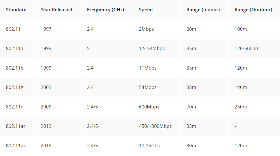
Note that these maximum data rates are theoretical. For many reasons you’re probably going to get much lower data rates than the theoretical maximums.
Refer to the following article for a deeper explanation: 802.11 Wireless Standards Explained
Service sets.
The 802.11 standard defines various types of service sets, which are groups of wireless network devices. The three primary types are:
-
Independent service sets.
-
Infrastructure service sets.
-
Mesh service sets.
Devices within a service set share a common identifier known as SSID, or service set ID.
The SSID, or service set identifier, is a human-readable name that serves to identify a specific service set. While it does not have to be unique, it is advisable to configure unique SSIDs. This practice simplifies the process of selecting the correct network when connecting.
Let’s look at the different types of service sets.
An IBSS, or independent basic service set, refers to a wireless network where two or more devices connect directly without utilizing an AP. Such networks are commonly known as ad hoc networks. They are suitable for specific use cases, like file transfers, exemplified by Apple’s Airdrop. However, ad hoc networks are not scalable beyond a few devices and are typically employed for limited purposes, such as quick file transfers.
A BSS, or basic service set, is a type of infrastructure service set where clients connect to each other through an AP rather than directly. In this configuration, the AP functions as the network infrastructure, interconnecting various wireless clients. Uniquely identifying the AP within the BSS is the BSSID, or basic service set identifier, which is the MAC address of the AP’s radio. It’s crucial to note that multiple APs can use the same SSID, but they must have different BSSIDs.
Wireless devices request association with the BSS, and those successfully associated are called clients or stations. Additionally, the concept of the BSA, or basic service area, is significant. This represents the region around the AP where its signal is effectively usable.
The distinction between a BSS and a BSA lies in their definitions and functionalities. A BSS, or basic service set, refers to a group of devices that are wirelessly connected through an AP. On the other hand, a BSA, or basic service area, pertains to the physical region surrounding the AP where devices can associate with the AP and join its BSS. It’s important to note that within a BSS, communication between clients occurs via the AP, and clients do not communicate directly with each other. In summary, a BSS is a group of devices, while a BSA defines the physical area around the AP where devices can associate with the AP’s BSS.
Traffic within a wireless LAN must pass through the AP even when the destination client is within range of the sender’s signal. To extend wireless LAN coverage beyond the range of a single AP and create larger networks, an ESS, or extended service set, is utilized. The extended service set represents the second type of infrastructure service set, facilitating the expansion of coverage and the connection of multiple APs to form a cohesive and extended network.
Clients can transition between access points (APs) within an extended service set (ESS) without the need to reconnect, ensuring a seamless Wi-Fi experience when moving between APs. This process is referred to as roaming, specifically when transitioning between two APs in an extended service set. It’s crucial to note that for effective roaming, there should be some overlap in the basic service areas (BSAs) of the APs, typically around 10 to 15 percent. This overlap is necessary to prevent potential connectivity loss when moving between APs within the extended service set.
An MBSS, or Mesh Basic Service Set, is employed in scenarios where running an Ethernet connection to every access point (AP) is challenging. In a mesh network, APs within the MBSS utilize two radios. One radio is dedicated to establishing a Basic Service Set (BSS) for wireless clients, facilitating their connection to the network. Simultaneously, the second radio is utilized to form the mesh network between the APs, creating a backhaul network. This backhaul network bridges traffic from AP to AP, enhancing connectivity in situations where traditional Ethernet connections are difficult to implement.
For instance, when a PC aims to send traffic to the Internet within an MBSS (Mesh Basic Service Set), it directs the data to its closest AP. Subsequently, the AP bridges the traffic from AP to AP over the backhaul network, ultimately reaching the switch. In this network, at least one switch is connected to the wired network, and it is designated as the RAP (Root Access Point). The RAP acts as a central point for managing the mesh network and linking it to the broader wired network, enabling smooth data transfer between the mesh APs and the Internet.
In this mesh network, the RAP holds a crucial role, while the other APs are designated as MAPs (Mesh Access Points). A protocol is employed to determine the optimal path for traffic through the mesh, akin to how dynamic routing protocols operate in determining the best path to a destination. In the context of most wireless networks, they function as extensions of the wired network infrastructure, with the AP serving as the intermediary between the two mediums. In 802.11, the upstream wired network is called the DS (Distribution System), and each wireless BSS or ESS is mapped to a VLAN in the wired network.
AP Operational Modes.
An access point (AP) has the capability to provide multiple wireless LANs, each distinguished by a unique SSID. This functionality mirrors how a switch can segment a single physical wired network into multiple VLANs. Each wireless LAN is mapped to a separate VLAN and connected to the network through a trunk.
Now, let’s explore additional modes in which APs can operate. First, an AP in repeater mode serves to extend the range of a Basic Service Set (BSS). The repeater retransmits any signal it receives from the AP, effectively expanding the coverage of the AP’s BSS. It’s important to note that a repeater with a single radio must operate on the same channel as the AP, potentially leading to reduced overall throughput on the channel. This reduction occurs because the repeater repeats the AP’s signals back to it using the same channel, effectively keeping the channel busy and cutting the effective throughput by 50%. However, a repeater with two radios can mitigate this issue by receiving on one channel and retransmitting on another, improving overall channel efficiency.
Moving on, an AP operating as a workgroup bridge functions as a wireless client of another AP. This mode allows the AP to connect wired devices to the wireless network, expanding the network’s capabilities.
There are two types of Workgroup Bridges (WGBs). The Universal WGB (uWGB) follows the 802.11 standard, enabling the bridging of a single device to the wireless network. On the other hand, Cisco’s proprietary version, simply termed WGB, goes beyond the standard and allows multiple wired clients to be bridged to the wireless network. In summary, this solution accommodates clients that lack wireless support, enabling them to connect to the wireless network through an Access Point (AP) operating as a Workgroup Bridge.
An outdoor bridge serves the purpose of connecting networks across extended distances without the need for a physical cable link. In this setup, APs utilize specialized antennas designed to concentrate the majority of the signal power in a specific direction. This directional focus allows the wireless connection to span longer distances than typical wireless connections.
The connection can take two main configurations. Firstly, it can be point-to-point, linking just two sites. Alternatively, it can be point-to-multipoint, where multiple sites establish connections to a central site. This forms a hub-and-spoke topology, providing flexibility in network design for various scenarios and requirements.
Wireless Architecture.
Before covering wireless architectures, we’ll take a quick look at 802.11 frame formats and types.
Frame formats.
The general MAC (Medium Access Control) frame format consists of a header, frame-body, and frame check sequence (FCS). The header holds information about the frame. The frame-body carries data that needs to be transmitted. The transmitter calculates the FCS over the header and frame-body. The receiver uses the FCS to confirm that the header and frame-body are properly received. The following diagram shows the structure of a general MAC frame.
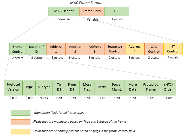
802.11 MAC Frame Format
Header: The frame header contains information about the where the frame is going, the data rate, cipher suite used to encrypt data frames, and more.
-
Frame Control (2 bytes): 16 bits long, this field provides information on the type and subtype of the 802.11 frame. It indicates the purpose and category of the frame.
-
Duration/ID Field (2 bytes): This field serves multiple purposes depending on the message type. It can indicate the duration (in microseconds) for which the channel is reserved for frame transmission. Alternatively, it may function as an identifier for the association or connection between the wireless client and the Access Point (AP).
-
Addresses (Up to four addresses): Depending on the message type, up to four addresses may be present in the frame:
Destination Address (DA): The final recipient of the frame.
Source Address (SA): The original sender of the frame.
Receiver Address (RA): The immediate recipient of the frame (not necessarily the final destination).
Transmitter Address (TA): The immediate sender of the frame (not necessarily the original source).
-
Sequence Control (2 bytes): Used to reassemble fragments and eliminate duplicate frames. It helps in maintaining the correct order of frames.
-
QoS (Quality of Service) Control (2 bytes): Prioritizes certain traffic based on Quality of Service requirements.
-
HT (High Throughput) Control: Introduced in 802.11n, this field enables high throughput operations, enhancing the overall data transfer rate.
Frame Body: The 802.11 frame body contains the actual data payload. This payload includes everything needed for specific applications or protocols. The body’s content is often encrypted for security, safeguarding the data’s confidentiality and integrity during transmission. The size of the frame body varies depending on the type of data being sent. For example, frames carrying voice traffic are generally smaller compared to those handling larger file downloads. This adaptability in size accommodates the diverse needs of different applications and ensures optimal performance across the wireless network, considering factors like connection speed and reliability.
Trailer: The trailer of the 802.11 frame incorporates a crucial element known as the Frame Check Sequence (FCS), employing a 32-bit cyclic redundancy check (CRC). This FCS serves as a robust mechanism to validate the integrity of the entire frame during its transmission over the wireless medium. Through a mathematical calculation, all values within the frame header and body contribute to the FCS field. Upon receiving the frame, the receiver performs the same calculation. If the calculated result diverges from the FCS field value, indicating potential tampering or corruption, the receiver deems the frame as damaged and rejects it. In such instances, an acknowledgment (ACK) frame is not dispatched, signaling the sender to initiate a retransmission due to the lack of confirmation. This scenario often arises in the presence of heightened interference or collisions. Importantly, frames with a defective CRC are typically discarded by the receiving station without forwarding them to the operating system, preventing their visibility in protocol analysers like Wireshark.
For a deeper understanding you can refer to the following article: 802.11 frames : A starter guide to learn wireless sniffer traces
Before 802.11 frame types, I want to introduce the 802.11 association process.
802.11 association process.
The process of connecting a station to an access point (AP) involves three distinct states. Initially, the station is neither authenticated nor associated with the AP. In the second state, the station achieves authentication with the AP but is not yet associated. Finally, in the third state, the station is both authenticated and associated with the AP. To transmit traffic through the AP, the station must successfully complete the authentication and association process.
Let’s look at a simple version of that process.
Initially, the station initiates a probe request to discover available APs and BSSs (Basic Service Sets), prompting the AP to respond with a probe response indicating its availability. This phase can be executed through either active scanning, where the station actively sends probe requests, or passive scanning, where the station listens for periodic beacon messages from APs. Despite obtaining information about the AP and its BSS, the station remains in the initial connection state, neither authenticated nor associated.
Then there is an authentication exchange. During this process, the station initiates communication with the AP by sending authentication information, often in the form of a password. The AP then verifies this information to authenticate the station. Upon successful authentication, the connection progresses to the second state, where the station is authenticated but not yet associated with the AP.
Following authentication, the next step involves an association request and response. In this phase, the station formally requests association with the AP, and the AP responds accordingly. Upon successful completion of the association process, the connection transitions to the final state, where the station is both authenticated and associated with the AP. At this point, the station is fully integrated into the wireless network and can begin sending traffic through the AP.
Note that all these communication steps: probe, beacon, authentication, and association, utilize the same type of 802.11 messages.
Frame types.
Within the 802.11 protocol, all frames are categorized into one of three types:
-
Management frames.
-
Control frames.
-
Data frames.
The first category is management frames, designed for the administration and control of the Basic Service Set (BSS). Examples of management frames include the beacon, probe, authentication, and association messages.
Probe request/response: As an integral part of both active and passive scanning processes, stations utilize probe requests with specific SSIDs, a wildcard, or no value (null) in the “SSID Parameter Set” field to explore wireless networks. In cases where the field is wildcard/null, the client seeks responses from any nearby APs with all SSIDs, achieved through a probe response frame. Conversely, when the probe request specifies a particular SSID, the client looks for responses only from APs supporting that specific SSID. The probe response frame acts as a targeted beacon sent to the probing station. While the probe response frame shares numerous fields with beacon frames, there are three distinctions: the absence of a Traffic Indication Map (TIM), a Quality of Service (QoS) capabilities information element, and any information elements requested by the station.
Beacon: Access Points (APs) employ beacon frames as vital messengers, dispatched at regular intervals known as the Target Beacon Transmit Time (TBTT). These frames serve a pivotal role in broadcasting fundamental information about the WLAN’s configuration. Within each beacon, details such as support for standards like 802.11k and 802.11r, cipher suites, Authentication Key Management (AKM) methods, and the necessity for protection mechanisms are meticulously conveyed. Information Elements (IE) embedded within the beacon frame act as signposts, indicating the presence or absence of specific configurations.
The second type is control. Control frames serve the purpose of controlling access to the medium, specifically the radio frequency. They play a crucial role in facilitating the delivery of both management and data frames. Examples of their functionality include the transmission of messages such as “request to send” and “clear to send,” which contribute to the effective and coordinated use of the communication medium.
ACK (Acknowledgment) messages are control frames used to confirm the successful receipt of a transmitted frame.
The third type of message is data. Data frames are used to transfer information or trigger an event. Not all data frames contain a payload, some are “null data frames” and only contain a header and trailer.
These are the frames used to send actual data packets.
For a deeper understanding you can refer to the following article: 802.11 Frame Types and Formats
APs deployment methods.
The deployment of wireless access points (APs) involves three main methods:
-
Autonomous.
-
Lightweight.
-
Cloud-based.
Each method represents a distinct approach to utilizing wireless APs in a network.
Autonomous:
Autonomous access points (APs) function as self-contained systems, operating independently without relying on a Wireless LAN Controller (WLC). This autonomy allows for individual configuration through various means, including console cable, remote access via telnet or SSH, and a web browser GUI accessible through HTTP or HTTPS. While this method is suitable for small networks, configuring APs individually becomes impractical in larger setups. Each AP requires manual configuration of radio frequency parameters, such as transmission power and channel selection. Security policies, like Access Control Lists (ACLs), are managed on a per-AP basis. Additionally, settings such as Quality of Service (QoS) are configured independently, with no centralized monitoring or management for the APs. In this setup, each AP operates as a standalone entity.
When utilizing autonomous APs, it’s crucial to connect each AP to the wired network through a trunk link. Even if only one Service Set Identifier (SSID) is provided, establishing a trunk connection is recommended. This is because management traffic, used for remote connections to wireless APs and other devices like switches, should reside in a separate VLAN. It follows best practices to segregate management traffic from regular data traffic by placing it in a distinct subnet and VLAN.
It is considered a poor practice to stretch each VLAN across the entire LAN, and there are compelling reasons behind this caution. One significant concern is the creation of large broadcast domains. Since each VLAN operates as an independent broadcast domain, when VLANs extend across the entire network, every broadcast message within a VLAN is indiscriminately flooded throughout the entire LAN. This results in increased broadcast traffic, potentially causing congestion and degrading network performance.
Another noteworthy issue is related to spanning tree protocols. When VLANs are excessively extended across the network, spanning tree algorithms may disable certain links to prevent loops. In contemporary network design, minimizing reliance on spanning tree is a key objective. Disabling links due to spanning tree decisions can lead to a reduction in overall available bandwidth, which is undesirable in modern high-performance networks.
Furthermore, the scalability and manageability of the network are compromised when the same VLAN spans multiple switches throughout a large network. Tasks like adding or removing VLANs become labor-intensive, especially in expansive network architectures where these operations must be performed across numerous switches.
In summary, autonomous APs can be used in small networks, but they are not viable in medium to large networks. A large network can have thousands of APs, and configuring and managing each of those APs one-by-one is not realistic. Finally, remember that autonomous APs can also function in the modes: repeater, outdoor bridge, or workgroup bridge.
Lightweight.
Now let’s talk about the next major deployment model for APs, lightweight APs.
In a split-MAC architecture, the responsibilities of an access point (AP) are divided between the AP itself and a Wireless LAN Controller (WLC). Lightweight APs handle real-time operations, including radio frequency traffic transmission, encryption/decryption, and beacon/probe transmission. Conversely, the WLC manages tasks such as RF management, security, QoS, client authentication, association, roaming, etc., centrally controlling these aspects for multiple lightweight APs. This architectural division optimizes network management and performance.
The WLC’s role extends beyond management, serving as a centralized configuration point for lightweight APs. This eliminates the need for individual CLI configuration of each AP, streamlining the process.
Note that the WLC is also used to centrally configure the lightweight APs. No more need to log into the CLI of each AP and manually configure them one-by-one, it’s all done centrally from the WLC.
The WLC can be positioned in the same subnet and VLAN as the lightweight APs or in a different one, offering flexibility in deployment. Authentication between the WLC and lightweight APs is ensured through X.509 standard digital certificates, providing network security by allowing only authorized APs to join.
Communication between the WLC and lightweight APs relies on the CAPWAP (Control and Provisioning of Wireless Access Points) protocol, an evolution of the Lightweight Access Point Protocol (LWAPP). The CAPWAP protocol establishes two tunnels between each AP and the WLC, facilitating effective communication and coordination in the split-MAC architecture.
Access Points (APs) and the Wireless LAN Controller (WLC) involves two distinct tunnels, each serving specific functions. The first is the control tunnel, utilizing UDP port 5246. This tunnel is responsible for configuring the APs, as well as managing and controlling their operations. It’s crucial to note that all traffic within this tunnel is encrypted by default, ensuring a secure communication channel.
On the other hand, the second tunnel is the data tunnel, operating on UDP port 5247. This tunnel is dedicated to routing all traffic from wireless clients to the WLC. Instead of directly reaching the wired network or other clients associated with the same AP, the traffic is required to traverse this tunnel to reach the WLC first. While, in reality, the traffic eventually passes through the wired network to reach the WLC, it is encapsulated with new headers to establish the tunnel, similar to the configuration of GRE and IPsec tunnels in wide-area network (WAN) scenarios.
It’s important to highlight that the traffic within the data tunnel is not encrypted by default. However, the option to configure encryption exists using Datagram Transport Layer Security (DTLS), a protocol similar to TLS (Transport Layer Security), but specifically designed for use with UDP.
In the context of Lightweight Access Points (APs) and Wireless LAN Controller (WLC) deployments, there is a notable distinction in the traffic flow compared to autonomous APs. Lightweight APs, operating under the CAPWAP protocol, direct all wireless client traffic through a data tunnel to the WLC. As a consequence, these APs connect to switch access ports rather than trunk ports. The need for multiple VLANs crossing the link is obviated, simplifying the network configuration.
Contrastingly, in an autonomous AP setup, each AP is required to connect to the network using a trunk link. VLANs are designated for each Service Set Identifier (SSID) the AP supports, along with a VLAN for network device management. Traffic from a wireless client follows a different path in this configuration. If the client intends to communicate externally, the frame is directed to its associated AP, which forwards it to the default gateway over the wired network. If the communication is within the same AP, the traffic remains within the wired network after being sent to the AP.
In the split-MAC architecture using Lightweight APs and a WLC, the dynamics change. The AP connects to switch access ports, and the WLC, acting as the border between the wired and wireless network, requires a trunk link to connect to the wired network. Traffic from a wireless client is initially sent to the AP, then tunneled to the WLC, and subsequently forwarded over the wired network to the default gateway. Even traffic destined for a host associated with the same AP follows a similar tunneled path through the WLC.
The adoption of a split-MAC architecture, utilizing Wireless LAN Controllers (WLCs) in conjunction with Lightweight Access Points (APs), offers several advantages, making it an attractive solution for network deployments.
First and foremost is scalability. The use of WLCs facilitates the establishment and maintenance of expansive networks comprising thousands of APs, a feat that would be impractical with autonomous APs. WLCs contribute to scalability by providing dynamic channel assignment, automating the selection of appropriate channels for each AP, and optimizing transmit power to ensure effective coverage without causing interference.
Moreover, the WLC introduces self-healing capabilities for wireless coverage. In the event of an AP failure, the WLC can dynamically increase the transmit power of neighboring APs, mitigating potential coverage gaps. The system also ensures seamless roaming, enabling clients to transition between APs without noticeable delays.
Client load balancing is another notable benefit of the split-MAC architecture. The WLC intelligently associates clients with the least-utilized AP when they are within the range of multiple APs, effectively distributing the load across the network.
Lastly, the centralized management provided by the WLC extends to security and Quality of Service (QoS) policies. This ensures a consistent and cohesive implementation of security measures and QoS parameters throughout the network, enhancing overall network management efficiency.
Lightweight APs offer diverse operational modes:
-
Local Mode: This is the default operational mode where the AP provides one or more Basic Service Sets (BSSs) for client association, following standard AP functionality.
-
FlexConnect Mode: While still offering BSSs for client association, FlexConnect mode adds extra capabilities. It enables the AP to locally switch and forward traffic between the wired and wireless networks in case of WLC tunnel disruptions, providing a failover mechanism.
-
Sniffer Mode: In this mode, the AP doesn’t provide a BSS for clients but is dedicated to capturing 802.11 frames. It sends these captured frames to a device running packet capture software for analysis, such as Wireshark.
-
Monitor Mode: Similar to Sniffer Mode, Monitor Mode doesn’t offer a BSS for clients. Instead, it is focused on receiving 802.11 frames to detect rogue devices. If rogue devices are identified, the AP can send de-authentication messages to disassociate them.
-
Rogue Detector Mode: This mode, though similar to Monitor Mode, operates differently. The AP doesn’t use its radio; instead, it listens to traffic on the wired network and receives a list of suspected rogue clients and AP MAC addresses from the WLC. By correlating this information, it can detect rogue devices.
-
SE-Connect (Spectrum Expert Connect): This mode doesn’t offer a BSS for clients but is dedicated to RF spectrum analysis on all channels. It sends information to software like Cisco Spectrum Expert on a PC to collect and analyze data, helping identify sources of interference.
-
Bridge/Mesh Mode: Similar to autonomous APs’ outdoor bridge mode, lightweight APs can function as a dedicated bridge between sites, even over long distances. A mesh can be established between access points.
-
Flex Plus Bridge: Combining FlexConnect functionality with bridge/mesh mode, this mode allows wireless access points to locally forward traffic even if connectivity to the WLC is lost, ensuring continuous operation.
Cloud-based.
The cloud-based AP architecture, exemplified by Cisco Meraki, combines the autonomy of individual APs with centralized cloud management. Through the Meraki dashboard, administrators can configure APs, monitor the network, and generate performance reports. While management and control information are sent to the cloud, user data, or regular traffic, is directed straight to its intended destination, such as a web or file server. This model strikes a balance between the autonomous AP and the split-MAC architecture, offering centralized management with direct data traffic flow.
WLC deployment models.
There are four main WLC deployment models, under split-MAC architecture:
-
Unified WLC Deployment: A standalone hardware appliance centrally located in the network, supporting up to approximately 6000 APs. Additional WLCs can be added for scalability, making it suitable for large enterprise campuses.
-
Cloud-Based WLC Deployment: The WLC operates as a virtual machine (VM) on a server, often in a private cloud within a data center. It supports around 3000 APs and can be scaled by adding more WLC VMs. Distinct from cloud-based AP deployment, this model involves lightweight APs with cloud-based WLCs.
Keep in mind that this is not the same as the cloud-based AP architecture we just discussed. In this case the APs are not cloud-based, they are lightweight APs. The ‘Cloud-based’ named here simply refers to where the WLC is.
-
Embedded WLC Deployment: The WLC is integrated within a switch, supporting up to about 200 APs. Additional switches with embedded WLCs are required for expanding the deployment. This model is appropriate for smaller campuses.
-
Cisco Mobility Express Deployment: Here, the WLC functionality is embedded within an AP, and other APs build internal CAPWAP tunnels to it. A Cisco Mobility Express WLC supports up to about 100 APs, and more APs with embedded mobility express WLCs are added to extend support. This deployment is ideal for small branch offices.
Wireless Security.
Encryption plays a role in all kinds of networks, but it’s especially important in wireless networks because a signal can be received by anyone within range of the sender, not just the intended recipient. And integrity means making sure that messages aren’t modified by any attackers while in transit.
Security is important in all networks. However, it’s even more essential in wireless networks. The main reason for that is: because wireless signals are not contained within a wire, any device within range of the signal can receive the traffic.
In wired networks, traffic is often only encrypted when sent over an untrusted network such as the Internet. You usually don’t encrypt wired traffic within the LAN, for example. But in wireless networks, it is very important to encrypt traffic sent between the wireless clients and the AP. That’s because, as I said before, any device within range of the signal can receive the traffic, but we want to ensure that only the intended recipient or recipients can read it.
Authentication:
All clients must be authenticated before they can associate with an AP. Authentication just means verifying the identity of a user and/or device. In a corporate setting, only trusted users and devices should be given access to the network.
However, a separate SSID which doesn’t have access to the corporate network can also be provided for guest users.
Those guest SSIDs have less strict authentication requirements, and probably only give access to the Internet, not to internal company resources. Not only should the AP authenticate the identity of clients, ideally the clients should also authenticate the AP to avoid associating with a malicious AP.
A malicious AP could trick users into associating with it, and then it can carry out attacks such as a man-in-the-middle attack.
There are multiple ways that authentication can be carried out, for example with a password, a username and password combination, or with digital certificates installed on the devices.
Remember that before associating with an AP, the client must first go through an authentication process like this.
Encryption:
Traffic sent between clients and APs, so any wireless traffic, should be encrypted so that it can’t be read by anyone except the AP and the client.
Encryption means scrambling up the message so that only the sender and the intended recipient can read it.
There are many possible protocols that can be used to encrypt traffic. It’s important that the sender and recipient use the same protocol, or else it would be like they are speaking different languages. The recipient wouldn’t be able to decrypt the sender’s messages.
Note that all devices on the wireless LAN will use the same encryption protocol, however each client will use a unique encryption and decryption key so that other devices can’t read its traffic.
Only the AP will have the appropriate key to decrypt the client’s traffic, the other clients won’t be able to decrypt it because they are using different keys. However there is also a ‘group key’ which is used by the AP to encrypt traffic it wants to send to all of its clients. All of those clients keep a copy of that group key so they can decrypt the traffic.
Integrity:
Integrity ensures that a message is not modified by a third party, it is not modified in-transit. So, the message that is sent by the source host should be the same as the message that is received by the destination host. To ensure that, a MIC (Message Integrity Check), is added to messages to help protect their integrity.
First, the sender calculates a MIC for the message and attaches it to the message. Just like encryption, there are many different protocols that can be used to calculate this MIC, and it’s important that the sender and receiver use the same protocol. Then the sender encrypts the message and MIC, and sends the frame. The recipient decrypts the message, and then independently calculates a MIC for the message, using the same protocol as the sender. It compares the two MICs, and if the MIC calculated by the sender and the MIC calculated by the recipient are the same, the recipient assumes the message wasn’t tampered with. Note that if the two MICs aren’t the same, if they are different, the message will be discarded.
So, instead of saying a MIC helps to protect the integrity of messages, it could be more accurate to say that it helps to identify if the integrity of a message has been compromised or not. If the integrity has been compromised, the message will be discarded.
Overview of various authentication methods.
The original 802.11 standard included two options for authentication. The first one is open authentication, which is very simple. The client sends an authentication request, and the AP accepts it. No questions asked, no credentials required. So, this is clearly not a secure authentication method.
The AP just accepts all authentication requests. However, it is still used today in combination with other authentication methods. After the client is authenticated and associated with the AP, it’s possible to require the user to authenticate via other methods before access to the network is granted. Think about Starbucks WiFi, or other public WiFi. You might be free to associate your device with the AP without even entering a password, but then you are probably required to login via a web page or something like that to authenticate. After that authentication, your device is granted access to the Internet.
So, open authentication itself is not secure at all, but it can be combined with other methods
Then the second method in the 802.11 standard is WEP (Wired Equivalent Privacy). Actually WEP is not just an authentication method, it provides encryption too. For encryption, it uses the RC4 algorithm.
WEP is a shared-key protocol, it requires the sender and receiver to have the same key, a shared key. Those WEP keys can be 40 bits or 104 bits in length. However those above keys are combined with a 24-bit initialization vector to bring the total length to 64 bits or 128 bits.
Now, usually longer key lengths are more secure, but WEP is NOT secure and can be easily cracked, regardless of the key length. You definitely should not use WEP on modern wireless networks.
But, how can WEP be used to authenticate a device? Here’s how it goes.
First, the AP sends a ‘challenge phrase’. This is just a series of bits, the actual contents don’t matter. The client then encrypts the challenge phrase using the WEP key and sends it back. Finally the AP takes the client’s encrypted challenge phrase and compares it to the AP’s own encrypted challenge phrase. If they match, it means the AP and client used the same key to encrypt the phrase, so the authentication is successful.
Basically, the AP is just testing if the client knows the shared key or not. Note that WEP can be used just to provide encryption, or to provide both encryption and authentication. If WEP authentication is not used, open authentication will be used and WEP will only be used for encryption.
However, open authentication on its own is not secure, and WEP is definitely not secure either as an encryption method or an authentication method. So, new wireless authentication methods were needed.
Now let’s look at those more secure methods, the different variations of EAP (Extensible Authentication Protocol).
EAP itself isn’t a single authentication protocol, but rather a framework which many other protocols, called EAP methods, are based on, such LEAP, EAP-FAST, etc.
What is EAP?
It is an authentication framework. It defines a standard set of authentication functions that are used by the various EAP methods. We will look at four of those methods: LEAP, EAP-FAST, PEAP, and EAP-TLS. Note that EAP is integrated with a protocol called 802.1X, which provides port-based network access control.
802.1X is used to limit network access for clients connected to a LAN or wireless LAN until they authenticate. Here are some specifics.
There are three main entities in 802.1X. First, the supplicant. This is the device that wants to connect to the network. Then there is the authenticator. This is the device that provides access to the network. Finally, the authentication server. This is the device that receives client credentials and permits or denies access.
802.1X is used in all kinds of networks, both wired and wireless, so definitely it is important know these three definitions, supplicant, authenticator, and authentication server.
In an 802.11 wireless LAN, the supplicant is the client that wants to connect to the network, for example a laptop. The authenticator is the device that provides access to the network, the access point. But actually, in a split-MAC architecture it’s the wireless LAN controller that manages the authentication, not the AP itself. And the authentication server is usually a RADIUS server.
Here’s how it works. The 802.11 wireless authentication required to associate with the AP is simply open authentication. Now the client is associated. However, it does not yet have full access to the network. The only traffic allowed from the client is traffic required for EAP authentication. And it is the authentication server that will check the client’s credentials and decide to permit access or deny access to the network. So, the WLC is now a middle-man in the authentication process.
The 802.11 authentication required to simply associate with the AP is open, but then there is the additional step of EAP authentication that is required to get access to the network.
Let’s look at some different EAP authentication methods used in wireless LANs.
The first is LEAP, lightweight EAP. It was developed by Cisco as an improvement over WEP.
Here’s how it works.
Clients must provide a username and password to authenticate. But in addition to that, mutual authentication is provided by both the client and server sending a challenge phrase to each other. In WEP, only the server sent a challenge phrase, but in LEAP both client and server send challenge phrases.
So, first challenge phrases are exchanged, then each device encrypts the other’s challenge phrase and sends it back, and they use that to authenticate each other like in WEP. To further improve the security, dynamic WEP keys are used. These are WEP keys that automatically change over time, to make it harder to crack the encryption.
However, like WEP, LEAP is considered vulnerable and should not be used anymore. Instead, you should use one of the next methods.
The next method is EAP-FAST, EAP flexible authentication via secure tunneling. This was also developed by Cisco. It consists of three phases. First, a PAC, protected access credential, is generated and passed from the server to the client. Like this. This PAC is like a shared key and is used in the next phase, to establish a secure TLS tunnel between the client and authentication server.
So, now there is a secure tunnel established that can be used for secure encrypted communications. The final step is that the client is authenticated within the TLS tunnel.
That’s EAP-FAST. The last two methods are similar to EAP-FAST, but different in some key ways.
Next is PEAP, protected EAP. Like EAP-FAST, it involves establishing a secure TLS tunnel between the client and server. But instead of a PAC, the server has a digital certificate. It will show its digital certificate to the client, and the client uses this to authenticate the server. This certificate is also used to establish the secure TLS tunnel. And because only the server provides a certificate for authentication, the client must still be authenticated within the secure tunnel.
One protocol that can be used for that authentication is called MS-CHAP (Microsoft Challenge Handshake Authentication Protocol).
So, that’s PEAP. Remember that EAP-FAST uses a PAC, but PEAP uses a digital certificate. However both involve establishing a secure tunnel and then authenticating the client inside of that tunnel.
And finally the last authentication method is EAP-TLS, EAP transport layer security. Whereas PEAP only requires the AS, authentication server, to have a certificate, EAP-TLS requires a certificate on the AS and on every single client. It is considered the most secure authentication method, but it is more difficult to implement than PEAP because every client device needs a certificate. That can add a lot of complexity, time, and effort. Because the client and server authenticate each other with digital certificates, there is no need to authenticate the client within the TLS tunnel.
However, the TLS tunnel is still used to exchange encryption key information.
To summarize, EAP-TLS is the most secure authentication method, but it takes more effort to implement, so many enterprises might prefer PEAP instead.
Encryption methods.
First up, [TKIP (Temporal Key Integrity Protocol)](Temporal Key Integrity Protocol - Wikipedia. As I said before, WEP was found to be vulnerable, however wireless hardware at the time was developed to use WEP.
So, a temporary solution based on WEP was needed until a new standard was created and new hardware was built. That temporary solution was TKIP. It’s based on WEP but adds various security features.
Just understand that TKIP is like a more secure version of WEP. So, TKIP uses a MIC to protect the integrity of messages.
Also a key mixing algorithm is used to create a unique WEP key for every frame, instead of each frame using the same key. This makes it harder to crack the encryption. The initialization vector, which I mentioned earlier, is doubled from 24 bits to 48 bits, which makes brute-force attacks to crack the encryption much more difficult. The MIC includes the sender MAC address, used to prove the identity of the frame’s sender. Also a timestamp is added, so attackers can’t do a replay attack.
Replay attacks involve re-sending frames that have already been sent.
Similarly, a TKIP sequence number keeps track of frames sent from a source MAC address. This also protects against replay attacks, because a frame will be dropped if the sequence counter is incorrect.
Just know that TKIP was developed as a more-secure temporary solution after WEP was found to be vulnerable. And know that TKIP is used in WPA, Wi-Fi Protected Access version 1.
Next up is CCMP (Counter/CBC-MAC protocol). It was developed after TKIP and is more secure. It is used in WPA2. Note that for a device to use CCMP, it must be supported by the device’s hardware. Old hardware built only to use WEP or TKIP cannot use CCMP.
It consists of two different algorithms to provide encryption and a message integrity check. For encryption, it uses AES counter mode. AES is the most secure encryption protocol currently available and is used all over the world by corporations, governments, etc. There are multiple modes of operation for AES, and CCMP uses what’s called ‘counter mode’ because it offers high performance, high speed.
Then it uses CBC-MAC, cipher block chaining message authentication code, as a message integrity check to ensure the integrity of messages. So, that’s how CCMP provides encryption and integrity.
Finally there is GCMP (Galois Counter Mode Protocol). It is more secure and more efficient than CCMP, and its efficiency allows higher data throughput than CCMP. It is used in Wi-Fi Protected Access 3.
Like CCMP, it consists of two algorithms. First, AES counter mode encryption. And then GMAC (Galois Message Authentication Code) which is used as a MIC to ensure the integrity of messages.
Now, with so many different authentication, encryption, and integrity methods:
Which ones should we choose?
Which combinations work together and which don’t?
And how can we know which hardware supports which standards?
To simplify things and create standard sets of protocols to be used, the Wi-Fi alliance developed the WPA (Wi-Fi Protected Access), industry certifications.
The Wi-Fi alliance has developed three WPA certifications for wireless devices, WPA, WPA2, and WPA3. Note that the first one is just called WPA, not WPA1.
For a device to be WPA certified, it must be tested in authorized testing labs. This is just like how the Wi-Fi alliance certifies devices for Wi-Fi 4, Wi-Fi 5, Wi-Fi 6, etc
They also certify devices for WPA, WPA2, and WPA3 security. All three of the WPAs support two different authentication modes.
First is personal mode, in which a pre-shared key, PSK, is used for authentication. For example, when you connect to a home Wi-Fi network, enter the password and are authenticated, that is personal mode. It’s common in small networks, such as SOHO (Small office/home office) networks.
Note that for security purposes, the PSK itself isn’t actually sent over the air. A four-way handshake is used for the authentication, and the PSK is used to generate encryption keys. If the devices use the same PSK to generate the encryption keys, they will be able to decrypt each other’s traffic, meaning that they will know that the other device is using the same PSK.
In addition to personal mode, there is enterprise mode. This is the mode that uses 802.1X with an authentication server. I introduced a few EAP methods and they are used with enterprise mode, although WPA doesn’t specify any specific method. So, all EAP methods are supported, such as PEAP or EAP-TLS.
Now let’s look at WPA, WPA2, and WPA3.
The first WPA certification was developed after WEP was proven to be vulnerable and it includes the following protocols. TKIP, which as you know is based on WEP, provides encryption and integrity. Authentication can be provided by 802.1X and EAP, when using enterprise mode, or by PSK when using personal mode. But WPA didn’t last very long. After more secure protocols and hardware were developed, WPA2 was released and it includes the following protocols.
CCMP is used to provide encryption and MIC. And again, authentication can be done via 802.1X using EAP or PSK. And finally in 2018 WPA3 was released. It uses GCMP for encryption and integrity. And once again supports 802.1X based or PSK based authentication. In addition to that, it offers several additional security features, here are a few examples. There is a feature called PMF, protected management frames.
It protects 802.11 management frames from eavesdropping and forging. Actually this was available as an optional feature in WPA2, but WPA3 makes it mandatory. Also, SAE (Simultaneous Authentication of Equals). It protects the four-way handshake when using personal mode authentication.
The last example is forward secrecy. It prevents data from being decrypted after it has been transmitted over the air. This protects against attacks in which an attacker captures wireless frames, and then tries to decrypt them later to read the contents.
That’s all I’ll say about the WPA certifications. Basically, they take the various security protocols, and package those protocols into standard sets. Hardware is then tested and certified to make sure it supports these standards.