First categorization is Cell level beams and User level beams and second categorization is Static beams and Dynamic beams.
Cell Level Beams:
Cell Level Beams are easy to understand with the initial UE access procedures. First of all UE has to synchronize with the cell by listening to SS (Synchronization signals ) and then UE will decode the BCH (Broadcast Channel). Then UE will go to Random Accesses Procedure which is the initial UE access channel to the network. There are physical allocations in frequency and time domain to achieve these initial procedures and we called them signals or channels. So Synchronization done by PSS and SSS ( Primary & Secondary Synchronization Signals). PBCH (Physical BCH) is caring broadcast channel to UE. These channels and signals are in broadcast mode. (Propagate over the entire cell radius).
The common thing in above all channels and Signals explained is “not belongs to specific user” , so we called them Cell level signals and channels. Now I guess, you understand the ‘Cell Level’ part of the topic. But what about ‘Beams’ part? This is the most interesting part of the topic. Because above Initial UE procedure in high-level perspective is same in Utran, eUtran and NR also. Well, the new thing is ‘Beams’ .
In NR, above Signals and Channels are in beams. To cover entire cell area, need multiple beams. In eUtrans , it was a single wide beam covering entire cell. But in NR , there are eight beams to cover 120 degree cell. But it can be less than eight also (I will discuss this in detail later with a new topic called ‘scenario based coverage’). Below picture is showing beam comparison between eUtran & NR from Horizontal view from sky.
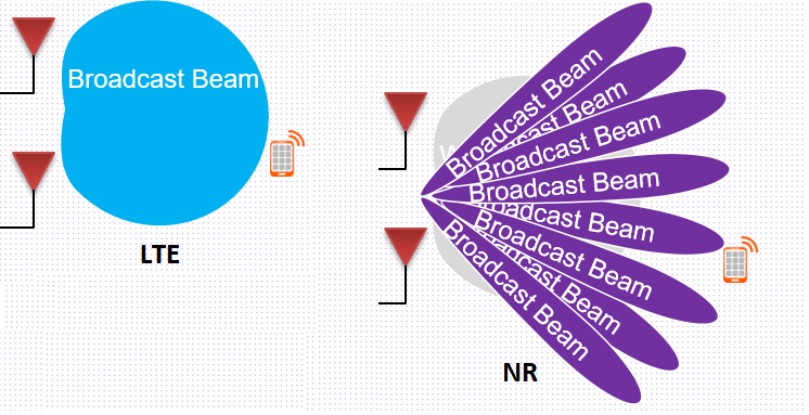
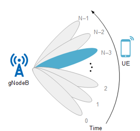
We called them SSBs (Synchronization Signal Beams). These beams are in scanning mode in UE side and sweeping mode in base station side means, each beam will be in allocated geographical direction at particular time frame. So UE will scan for one of the beam as UE location in the sector (Selection of optimal beam). I will discuss beam swapping in more deeper details in a upcoming article. For the moment I will stick in to beam categorization which the scope of this article. Broadcast beams are generated by Base station according to configuration. So these beams will be fixed once they formed first time. This is how the second categorization is come into picture. So all Cell Level beams are Static beams.
User level beams:
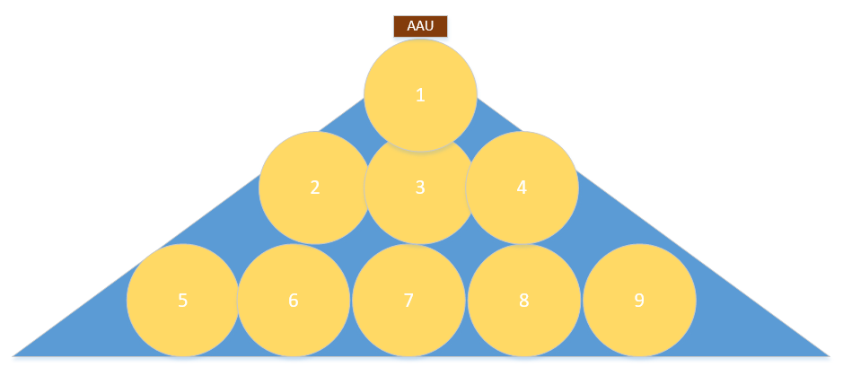
User Level beams are the opposite of the Cell level beams. User Level beams are allocated to specific user. There are S tatic and D ynamic beams under user level beams. In 64T64R antenna array can form 32 static beams to cover 120 degree sector. But these 32 beams are basically defining a geographical location of the sector in vertical and horizontal space. So the most liberal way is to call them beam position rather than beams. Main difference between user beams and cell beams is the beam width. Cell beams are wider beams in horizontally and vertically. One Cell beam can cover lager space in horizontal plan and entire vertical plane. But User beams are narrow and different beams required to cover horizontal and vertical space. Below picture is an example just to understand the concept (blue area is the sector coverage and yellow circles are the beams) and this is how beam spots on a flat surface will look like from sky view . In reality there are 32 beams in predefined positions. By the way in NR, sector coverage can be controlled, it doesn’t need to be 120 degree sector always as we know from other generation of technology. So the beam positions will be adjusted according to sector pattern. That is the beauty of Massive MIMO. I will cover coverage based beam forming in a another article.
These static beams are also called CSI-RS beams and beam allocation for a user will be done by understanding the of direction Sounding reference signal (SRS) coming from user. We will discuss these terms in detailed in a another article.
So what about Dynamic beams mention above? here is the deal. Static beam allocation to UE is based on initial UE access to cell. Then based on UE signal quality, more optimized beams will be allocated for higher throughput (SU-MIMO layers) and beams will be more optimized and narrower for interference reduction. Also beam steering will be done according to user movements. So the concept of predefined beam location will be break here. That is how D ynamic beams coming to picture. Hope you understand beams categories in NR now. See you in a another article soon!