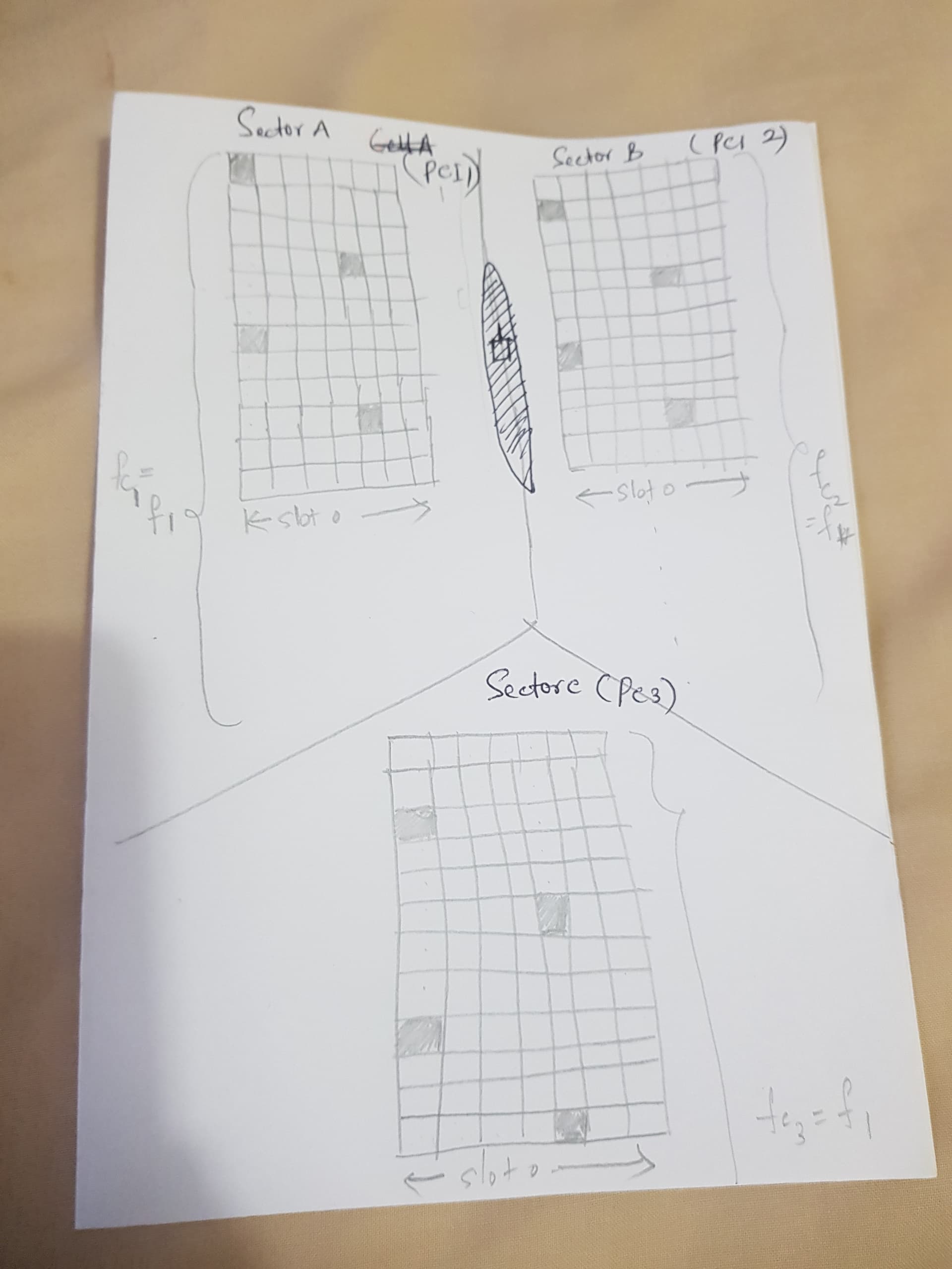
And lets say all the sectors have same Bandwidth and same carrier (and centre frequency).
Now, queries:
Is the above a valid configuration?
If its valid, then for UEs at the sector border (as depicted in picture), where the Ref signal strengths of Sector A and Sector B are almost equal, can they decode the serving cell REs?
Finally, as there is only one instance of RRC in the eNB, how can it handle 3 sectors? Does it create 3 instances for each cell?
This may be simple question, but will help me a lot .
I am not sure what you are trying to show by those resource blocks in sectors. I think you are mixing two things there. Reference signals are shifted like that in case of different MIMO configurations (ie number of radio/antenna ports).
At the cell border UEs decode PSS and SSS → PCI, that will help to decode MIB etc.
As a radio planning engineer you are not really concerned by this low level design. You will likely be doing PCI and RACH planning only.
As for PCI planning there are plenty of resources on internet, but basically PCI consists of PSS and SSS sequence. General rule of thumb is you keep single SSS on site while each sector has a different PSS. PSS 0,1,2 is first to used by UE to sync to cell thus no overlapping sectors should have same PSS (ideally), although the negative impact here is quite negligible.
And of course same PCI shouldn’t be on nearby cells. There are other fine tuning requirements like mod 6 and mod 30, but what I have said above is basics that you need to do your job, everything else is extra.
eNB handles multiple sectors/cells and each cell has it’s own independent RRC.
Hi @Londynan, Thankyou very much for the response.
Im trying to show each of those sectors will have different PCI. So based on that, the reference signals position varies ?
I know PSS, SSS is used to derive the PCI. But all I am trying to understand is if the same frequency can be used for two sectors of the same cell. Will it cause the issue in decoding PSS/SSS at the cell boarders(or segment boarders) with the same frequency ?
But having independent RRC contradicts the spec ? (NO where it is mentioned that each segment will have a different RRC instance ) ?
Hello, those reference signals are shifted based on MIMO configuration and these are CRS, PCI is not directly related to it.
Yes PSS/SSS are located on same frequency and in theory it should “clash” but you must understand that PSS/SSS are uncorrelated code sequences therefore UE does decode strongest PSS/SSS even through some “interference” of other cell.
That I am not sure what you mean, I would have to look it up in specs. Nevertheless as a network planning engineer this is completely out of your interest (RRC control, signaling in eNB etc.)
I thought the number of reference signals depends on the MIMO configuration. And the PCI planning will make sure that these reference signals doesnot overlap for the neighbours. May be we can consider a cell with two antenna ports and and say PCI=N1, and neighbour cell with eg two ports and PCI=N2… The PCI assignment need to make sure the reference signals does not overlap on these two cells (irrespective of number of ports these cells have ) . This is my understanding ? Is this correct.
thanks
pdk
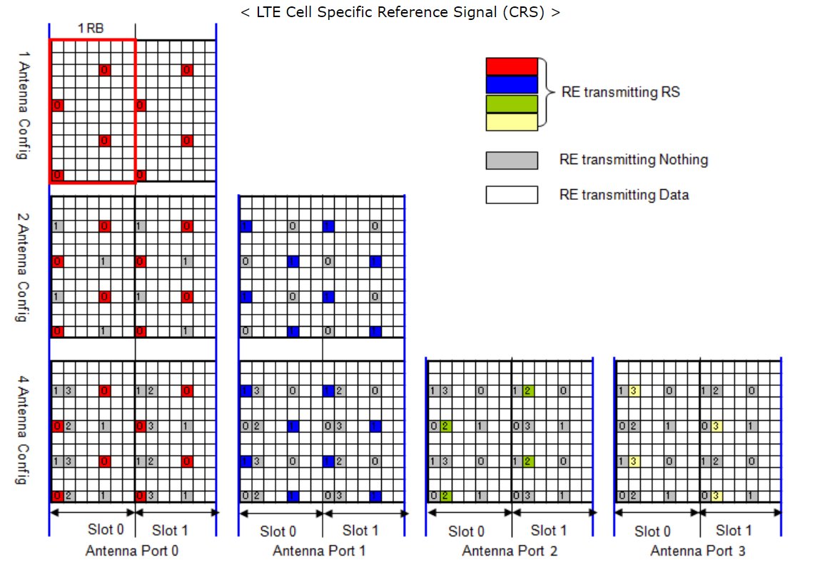
yes number of reference signals depends on MIMO. These reference signals do not overlap within cell, here is a nice picture from Sharetechnote. Essentially each port is transmitting its own CRS while the other ports are quiet.
CRS are in every resource block and there is no space to move them around, therefore they do overlap with neighbours and this causes low SNR. This is essentially unavoidable because you need a certain cell overlaps for handovers… But you must disconnect CRS from PCI, CRS is used to demodulate your signal(RB) and not to identify the cell. PCI is formed by a separate PSS and SSS, UE synchronizes to strongest PSS&SSS then identifies the cell.
interesting take of this guy, but I can’t say I fully agree with everything said there. Again, first you need to understand the practical difference between PCI and reference signals. As was said in video UE first performs cell search and for that it needs to synchronize to nearby cell, therefore UE runs correlation on all PSS and SSS sequences. PSS first by the way. After it gets PSS and SSS then it has PCI - unique cell identification.
For your PCI planning you need to follow those basic rules there:
Avoid any PCI collisions and confusions on “nearby” cells. Meaning none of the “nearby” cells should have same PCI
Ideally avoid same PSS on overlapping sectors since the PSS is the first sequence UE is trying to scan/detect and so you want to have it as clean as possible (especially handovers for fast moving UEs). This is his second method there in video.
Regarding that reuse distance, I would say it should be more as this equation would clear collisions but not confusions. You can easily calculate what is maximum achievable PCI reuse distance in given area and then re-plan entire area to get as close as possible to that upper boundary. That way you can do audit how good PCI plan is.
This PCI mod3/mod 6 collision of RS is valid only for 1TX as was said there, but in reality you will be doing 2Tx or 4Tx so there will be always interference, it is unavoidable! Therefore you don’t need to be bothered by it, as network engineer you plan PCIs as per above and you try to minimize interference (SNR) by cell overlaps. PCI planning is very simple
 Planning - LTE")