Attach Sequence for LTE Radio Explained!
![]() Steps (1) to (3): When the terminal establishes a radio control link for sending and receiving control signals with the eNodeB, it sends an attach request to the MME. The terminal and MME perform the required security procedures, including authentication, encryption and integrity.
Steps (1) to (3): When the terminal establishes a radio control link for sending and receiving control signals with the eNodeB, it sends an attach request to the MME. The terminal and MME perform the required security procedures, including authentication, encryption and integrity.
![]() Steps (4) to (5): The MME sends an update location request message to the Home Subscriber Server (HSS), and the HSS records that the terminal is connected under the MME.
Steps (4) to (5): The MME sends an update location request message to the Home Subscriber Server (HSS), and the HSS records that the terminal is connected under the MME.
![]() Step (6): To begin establishing a transmission path to the default PDN, the MME sends a create session request to the S-GW.
Step (6): To begin establishing a transmission path to the default PDN, the MME sends a create session request to the S-GW.
![]() Steps (7) to (8): When the S-GW receives the create session request from the MME, it requests proxy binding update to the P-GW. The P-GW allocates an IP address to the terminal and notifies the S-GW of this information in a proxy binding acknowledgement message. This process establishes a continuous core-network communications path between the P-GW and the S-GW for the allocated IP address.
Steps (7) to (8): When the S-GW receives the create session request from the MME, it requests proxy binding update to the P-GW. The P-GW allocates an IP address to the terminal and notifies the S-GW of this information in a proxy binding acknowledgement message. This process establishes a continuous core-network communications path between the P-GW and the S-GW for the allocated IP address.
![]() Step (9): The S-GW prepares a radio access bearer from itself to the eNodeB, and sends a create session response signal to the MME. The create session response signal contains information required to configure the radio access bearer from the eNodeB to the S-GW, including information elements issued by the S-GW and the IP address allocated to the terminal.
Step (9): The S-GW prepares a radio access bearer from itself to the eNodeB, and sends a create session response signal to the MME. The create session response signal contains information required to configure the radio access bearer from the eNodeB to the S-GW, including information elements issued by the S-GW and the IP address allocated to the terminal.
![]() Steps (10) to (11) and (13): The MME sends the information in the create session response signal to the eNodeB in an initial context setup request signal. Note that this signaling also contains other notifications such as the attach accept, which is the response to the attach request. When the terminal receives the attach accept in Step (11), it sends an attach complete response to the MME, notifying that processing has completed.
Steps (10) to (11) and (13): The MME sends the information in the create session response signal to the eNodeB in an initial context setup request signal. Note that this signaling also contains other notifications such as the attach accept, which is the response to the attach request. When the terminal receives the attach accept in Step (11), it sends an attach complete response to the MME, notifying that processing has completed.
![]() Step (12): The eNodeB establishes the radio data link and sends the attach accept to the terminal. It also configures the radio access bearer from the eNodeB to the S-GW and sends an initial context setup response to the MME. The initial context setup response contains information elements issued by the eNodeB required to establish the radio access bearer from the S-GW to the eNodeB.
Step (12): The eNodeB establishes the radio data link and sends the attach accept to the terminal. It also configures the radio access bearer from the eNodeB to the S-GW and sends an initial context setup response to the MME. The initial context setup response contains information elements issued by the eNodeB required to establish the radio access bearer from the S-GW to the eNodeB.
![]() Steps (14) to (15): The MME sends the information in the initial context setup response to the S-GW in a modify bearer request signal. The S-GW completes configuration of the previously prepared radio bearer from the S-GW to the eNodeB and sends a modify bearer response to the MME.
Steps (14) to (15): The MME sends the information in the initial context setup response to the S-GW in a modify bearer request signal. The S-GW completes configuration of the previously prepared radio bearer from the S-GW to the eNodeB and sends a modify bearer response to the MME.
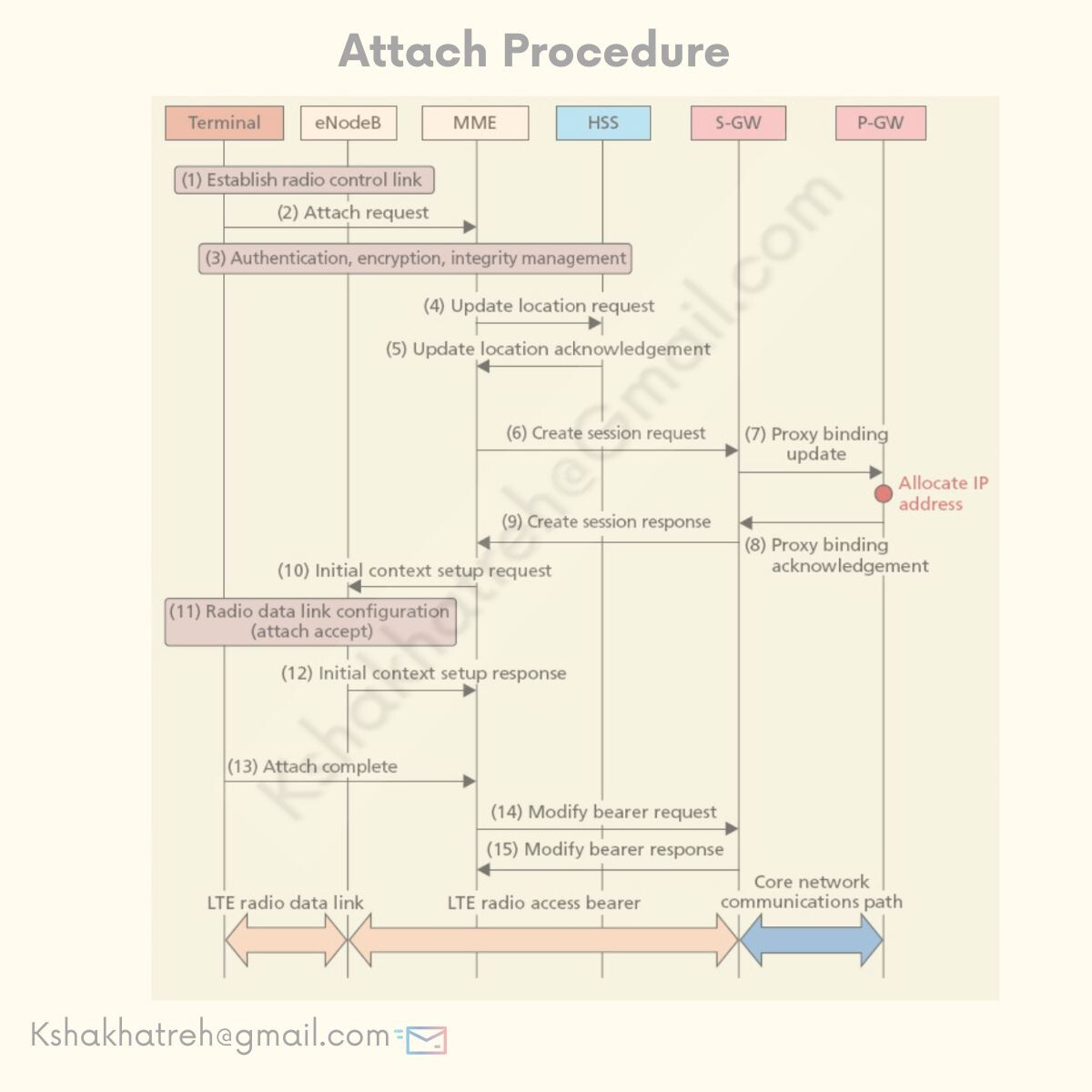
Through these steps, a communications path from the terminal to the P-GW is established, enabling communication with the default PDN.
If the terminal performs no communication for a set period of time, the always-on connection function described above releases the radio control link, the LTE radio data link, and the LTE radio access bearer, while maintaining the core network communications path.
After the terminal has established a connection to the default PDN, it is possible to initiate another connection to a different PDN. In this way it is possible to manage PDNs according to service.
For example the IMS PDN, which provides voice services by packet network, could be used as the default PDN, and a different PDN could be used for internet access.
LinkedIn: ![]()