Hi experts,
I’m recently confused about the CSI_RS in connected mode. So the SSB will still be transmitting due to the need of synchronization even in connected mode. So does gNB still do beam sweeping periodically even the user and gNB are connected? If it does, is the beam sweeping based on SSB or CSI-RS? Also, I read some books and papers said that the CSI-RS are framed in the PDSCH which means that CSI-RS are surrounded by data, but some says it’s independent from PDSCH and in time domain it’s right after the SSB.
If there is beam refinement in connected mode periodically, then it’s based on CSI-RS (RSRP). Also CSI-RS is used for channel estimation (feedback includes PMI RI and CQI…), are these two CSI-RS the same in time and frequency domain or they are separated?
SSBs are for all UEs. gNB transmits SSB beams by means of beam sweeping, no matter a specific UE is connected or not.
Sorry I’m still a little confused. So for the UEs who are already connected, do they still use SSB to do synchronization periodically and measure the RSRP for better beams so that they can do beam switching?
Yes they do. But for UEs in connected mode, they can use CSI-RS beams for more accurate beam selection. In my opinion, SSB is for first-step beam selection, and CSI-RS is for further.
Thank you for your response, that’s really helpful. I also got another question, as you mentioned CSI-RS beams, is CSI-RS framed in the PDSCH data or they are separated from the PDSCH data and are transmitted like pilots with no user data around? If the CSI-RS is framed in PDSCH data, does that mean when gNB is doing CSI-RS beam sweeping, some of the user data are beamformed in different directions?
CSI-RSs are transmitted in the BWP assigned to a UE, independently of PDSCH. The UE can be assigned different CSI-RS resources for different use. PDSCH beam can be formed according to CSI-RS beam measurement result (CSI report). PDSCH resource should be punched at CSI-RS REs.
White REs can be PDSCH data, or nothing, depending on this area is scheduled or not.
Thanks ![]() Then if we beamformed CSI-RS in different directions, does’t it mean that the surrounded data will also be beamformed in different directions? Then the quality of communication will change as well. Or the beam refinement using CSI-RS beam doesn’t consist user data, and the CSIRS in the pic is used for channel estimation, not for beam refinement?
Then if we beamformed CSI-RS in different directions, does’t it mean that the surrounded data will also be beamformed in different directions? Then the quality of communication will change as well. Or the beam refinement using CSI-RS beam doesn’t consist user data, and the CSIRS in the pic is used for channel estimation, not for beam refinement?
Data is on PDSCH, doesn’t follow CSI-RS. REs carrying CSI-RS carry no data, while surrounding REs can carry PDSCH data. CSI-RS for the specific UE transmit in the same direction as PDSCH do.
Thank you for your answer. Yes, I understant that the surrounding REs carries data and need to be beamformed in the same direction as the CSI-RS. But what about beam refinement? I suppose that the beam refinement is based on CSI-RS beam sweeping, but if the CSI-RS is surrounded by data, doesn’t mean that the data is kind of like sweeping in different directions in beam refinement as well? Or the frame in beam refinement doesn’t show like what the pic shows.
There are different CSI-RS types for a specific UE, some for time/frequency tracking, some for CSI reporting, some for beam management. For beam refinement purpose, I think the UE only receive it on demand, like the time RRC connection is just established, or reestablished, then the beam follows UE’s movement. That’s my point.
Oh I see. Thank you for your response, it’s really helpful. I thought the CSI-RS only shows the way in the pic. Now I know that they can be for different kinds of use and have different frame sturucture. Thank you sir! Have a nice day ![]()
Thanks in advance
your questions were my question and Mr. upf’s answers were so helpful
Thanks sir , it was so useful
One way to look at it is like below.
gNB sends the CSI-RS in the downlink direction (NZP or ZP), and asks the UE, measure these and compare them to the pre-defined sequence and based on the errors, send me the closest codebook entry for this particular channel condition. The UE provides this information to the gNB from the codebook and then gNB uses this information to beam-form the data for this particular UE.
Yes, I suppose that’s one way to look at the CSI-RS, so UE provide CSI-RS report with RI, PMI… But I also read something that said the gNB could determine whether to use the PMI in the feedback because even UE gives gNB a recommendation of the preferred PMI, gNB can still don’t use it. This kind of CSI_RS can be considered as the reference signals. I also wonder that with this kind of CSI-RS being transmitted, is there still other kind of CSI_RS for beam training? Because even the UE is in connected mode, considering its mobility, gNB may still need to do beam sweeping to find the best beam, and the question is: does the beam sweeping use SSB or CSI_RS or both in mmWave, also is it periodically, instead of framed in data like the previous kind of CSI_RS that can be considered as reference signals, the beam sweeping kind are pilots, what does the frame structure of it looks like(I assume it should be different from the previous kind)?
Let me breakdown your comment and try to answer it individually.
But I also read something that said the gNB could determine whether to use the PMI in the feedback because even UE gives gNB a recommendation of the preferred PMI, gNB can still don’t use it.
UE provides the response to the CSI measurement and it is as per the gNB scheduler to use this information as is or modify it based on the overall settings. For example, the UE may be reporting a rank of 3 but the gNB may decide to give the UE a rank of 1. (To increase MUMIMO pairing, decrease interference, or based on low traffic demand or to converge to a lower bler etc…)
This kind of CSI_RS can be considered as the reference signals. I also wonder that with this kind of CSI-RS being transmitted, is there still other kind of CSI_RS for beam training?
Now, first of all, we should know that CSI-RS is infact a RS (Reference signal). The key difference between the LTE reference signal and CSI-RS of 5G is that CSI-RS is configured for UEs individually. Hence, when the UE is measuring these signals and reporting back the channel conditions (PMI+RI+LI+CQI+~PTI), then essentially the gNB gets the directionality information (beam-forming related) as the returned channel information helps the gNB to obtain the correct phase+amplitude combinations to enhance the beam in that particular direction. Another point to note is that CSI-RS can be configured as different sets for different UEs and so better beam management can be done like this.
Because even the UE is in connected mode, considering its mobility, gNB may still need to do beam sweeping to find the best beam
Beam sweeping is only supported for SSB. CSI-RS or downlink data uses the channel weights to try to provide a directional beam of data to each users and this is called beam-forming.
and the question is: does the beam sweeping use SSB or CSI_RS or both in mmWave, also is it periodically, instead of framed in data like the previous kind of CSI_RS that can be considered as reference signals, the beam sweeping kind are pilots, what does the frame structure of it looks like(I assume it should be different from the previous kind)?
As mentioned above, beam sweeping is only for SSB. In mmwave, the number of beams that can be sweeped by the same cell are higher compared to the FR1. (Upto 64 in contrast to 8 for 3.5GHz).
Beam sweeping is periodical as SSB beams are being broadcasted. Visually think of it like a Lighthouse rotating the source of light counter-clockwise.
For frame structure, mmwave vs. non-mmwave will not be different. Traditionally, the term frame structure mainly corresponds to the symbols, slots, half-frames, and frame timings. From the content of the frame perspective, mmwave will have higher numerology so the frame would look visually compressed when compared to FR1, but channel wise it would be similar to FR1 TDD cells.
I hope some of it is helpful for your understanding. Please post any followup questions in case.
Thank you sir, it’s really helpful.
I always thought there exist both beam sweeping and beamforming for CSI-RS. Because I saw the simulation in matlab, NR Downlink Transmit-End Beam Refinement Using CSI-RS - MATLAB & Simulink, it looks like there are CSI-RS beam sweeping. So I previously thought that there are CSI-RS sweeping after SSB for beam refinement, and CSI-RS beamforming in the PDSCH for channel estimation. After reading your answer, it seems like there is only CSI-RS framed in PDSCH and beamformed for both refinement and channel estimation, right?
I always thought there exist both beam sweeping and beamforming for CSI-RS. Because I saw the simulation in matlab, NR Downlink Transmit-End Beam Refinement Using CSI-RS - MATLAB & Simulink, it looks like there are CSI-RS beam sweeping.
Thanks for pointing out this resource. I will refer to the procedure where the sweeping is mentioned alongwith CSI-RS.
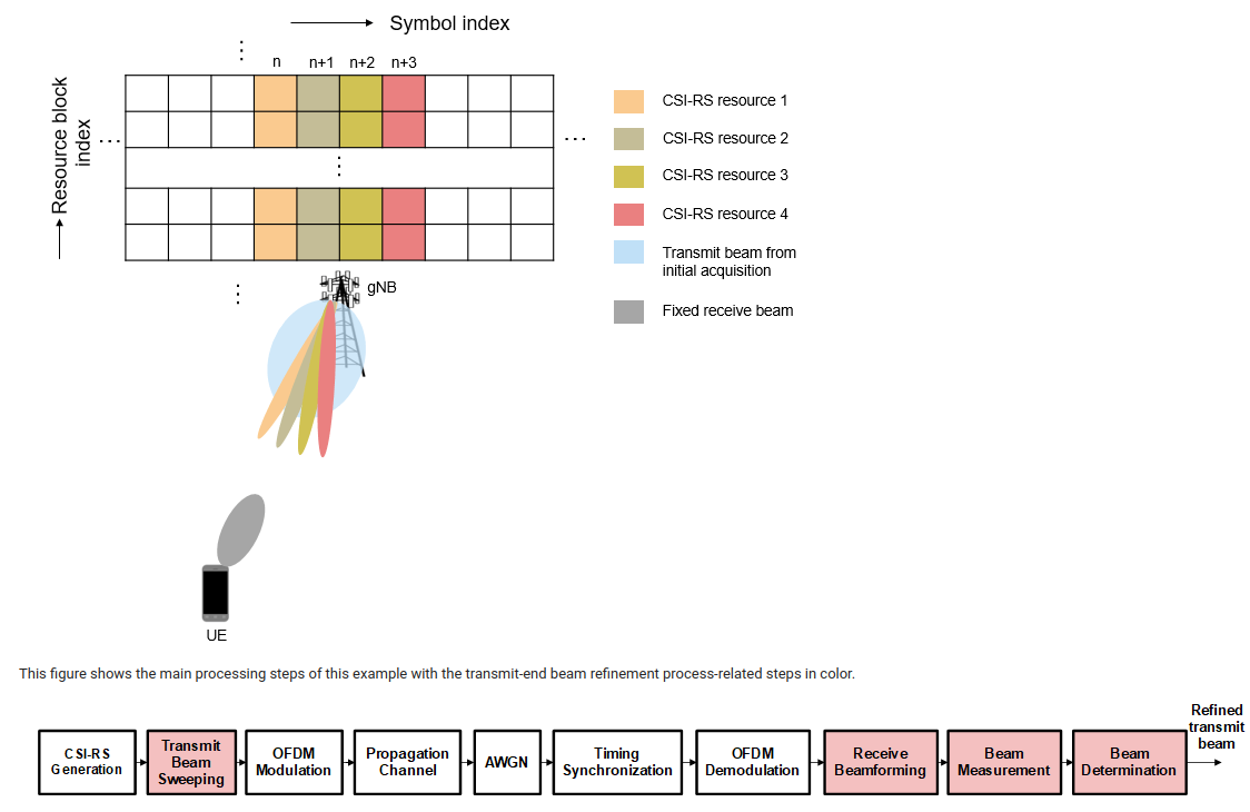
Procedure 3 (P-3): This procedure focuses on receive-end beam adjustment, where the beam sweeping happens at the receive end given the current transmit beam. This process aims to find the best receive beam, which can be a neighbor beam or a refined beam. For this procedure, a set of reference signal resources (NZP-CSI-RS for downlink and SRS for uplink) are transmitted with the same transmit beam and the UE or gNB receives the signal using different beams from different directions covering an angular range. Finally, the best receive beam is selected based on the RSRP measurements on all receive beams.
What they are referring to here is that if the gNB can afford it, then it will send the CSI-RS different sets to the same UE and based on the received channel characteristics, the gNB can now refine the beam. The diagram below can be helpful to understand how we are allocating different CSI resources to the UE so that at the cost of overhead, we can potentially refine the beam better.
In my opinion and previous readings, this is primarily known as beam-refinement. Beam-sweeping is used to denote the constant sweeps which are made by the SSB. However, if CSI is used this way, you can also refer to it as a sweep for a particular user.
Diagram to show that we assigned different CSI resource sets to the same UE
