The Open Systems Interconnection (OSI) model is a conceptual framework that divides network communications functions into seven layers each responsible for specific functions. Sending data over a network is complex because various hardware and software technologies must work cohesively.
The OSI data model provides a universal language for computer networking, so diverse technologies can communicate using standard protocols or rules of communication. Every technology in a specific layer must provide certain capabilities and perform specific functions to be useful in networking. Technologies in the higher layers benefit from abstraction as they can use lower-level technologies without having to worry about underlying implementation details.
The layers 1 and 2 of the model are given next.
Layer 1: Physical Layer
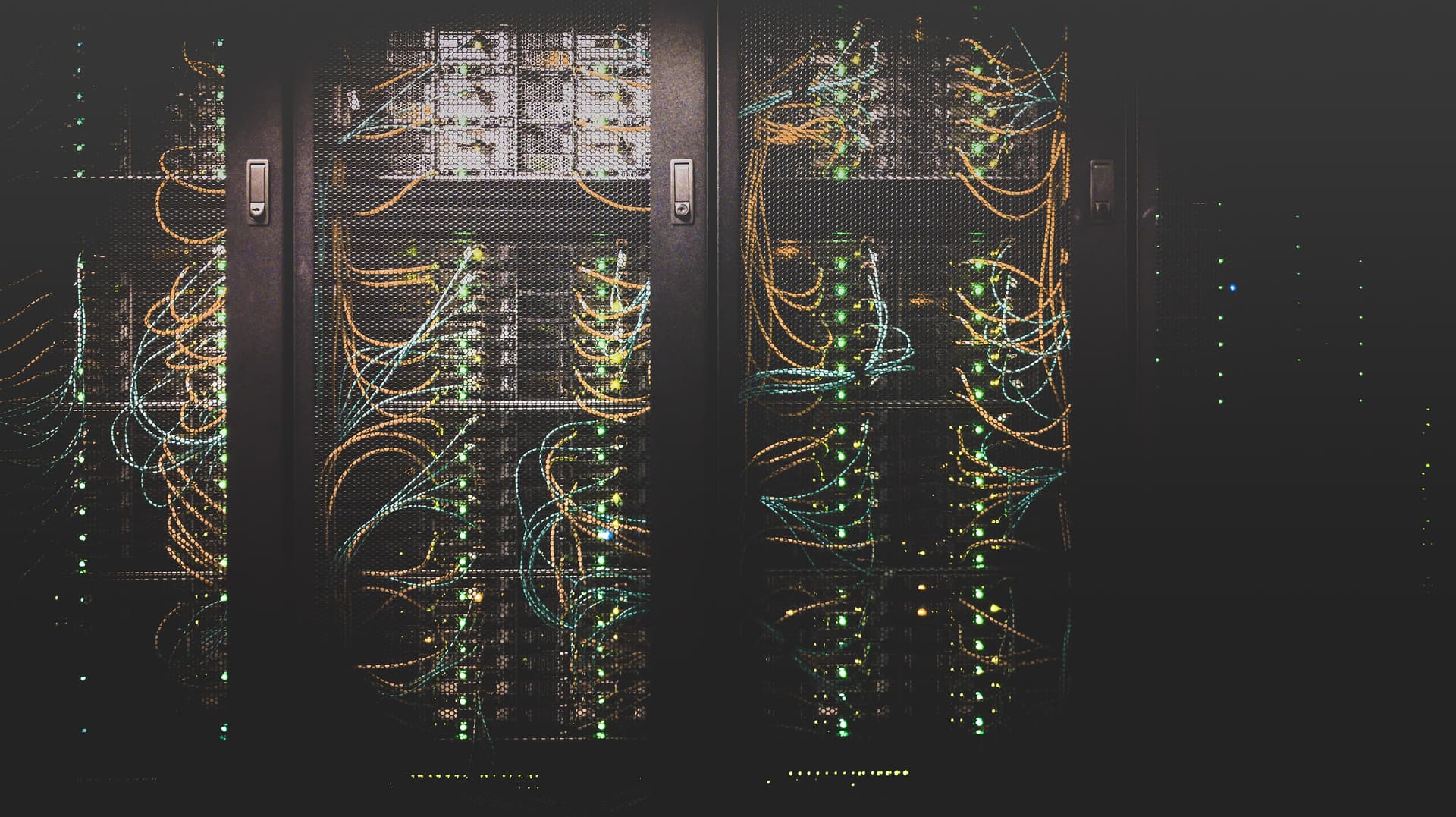
The Physical Layer refers to the physical communication medium and the technologies to transmit data across that medium. At its core, data communication is the transfer of digital and electronic signals through various physical channels like: fiber-optic cables, copper cabling, and air.
The Physical Layer deals with the actual physical connection between devices. Key aspects and functions include:
Bit Representation:
The Physical Layer is where the raw bitstream is physically transmitted over a physical medium. This includes: Signal encoding (translating bits to electricity, light, or radio signals) and Clocking (controlling the rates at which they are sent over the chosen medium).
Wiring Standards:
Various standards like Ethernet, USB, and HDMI govern the physical connectivity between devices. These standards dictate the type of cables, connectors, and signalling methods used.
Cable Types:
- Coaxial Cable.
- Twisted Pair: Shielded Twisted-Pair (STP) and Unshielded Twisted-Pair (UTP).
- Fiber-Optical Cable: Single-Mode Fiber (SMF) and Multimode Fiber (MMF).SMF: Extremely fast in terms of network speed and can carry signals media for longer distances than MMF. For this reason, this type of fiber is the backbone of the Internet, and is also used for transatlantic connections.MMF: It can be bent more than SMF which gives greater flexibility for installation. Can support data rates for up to 100Gbps but is limited in distance. Less costly than SMF
- Ethernet Copper Cables: Cat3,Cat4,Cat5,Cat5E,Cat6,Cat6A,Cat7,Cat8
Ethernet Connectors:
- Copper-based standards: RJ45, GG45.
- Fiber connections: MT-RJ, SC, LC
Synchronization:
Synchronizing bits: For two networked devices to successfully communicate at the physical layer, they must agree on when one bit stops and another bit starts. Synchronization ensures that devices on the network are operating in harmony. It involves synchronization of data bits; both, sending and receiving devices are linked, allowing data to transmit and be received in the correct order at the correct rate, coordinating the timing of data transmission to avoid conflicts.
The clocking process ensures that the sender and receiver are synchronized, allowing for reliable communication over the chosen medium.
Two basic approaches to bit synchronization include:
Asynchronous: A sender indicates that it is about to start transmitting by sending a start bit to the receiver. When the receiver sees this, it starts its own internal clock to measure the subsequent bits. After the sender transmits its data, it sends a stop bit to indicate that it has finished its transmission.
Synchronous: This approach synchronizes the internal clocks of both the sender and the receiver to ensure that they agree on when bits begin and end. A common approach to make this synchronization happen is to use an external clock (for example, a clock provided by a service provider), which is referenced by both the sender and the receiver.
Physical topology: Physical topology defines the actual layout of the network, including the arrangement of devices and the type of connections between them. Common topologies include: bus, ring, star, and mesh.
Bandwidth: The two fundamental approaches to bandwidth usage on a network are broadband and baseband. The Physical Layer differentiates between broadband and baseband transmission.
Baseband and broadband are networking terms that describe whether a given signal gets the medium to itself or whether it has to share the wire with other signals.
Broadband: Broadband technologies divide the bandwidth available on a medium into different channels. Different communication streams are then transmitted over the various channels.
Baseband: Baseband technologies, in contrast, use all the available frequencies on a medium to transmit data. Ethernet is an example of a networking technology that uses baseband.
Multiplexing Strategy: Multiplexing combines multiple signals into a single transmission medium for efficient data transfer. Multiplexing is a technique employed at this layer to efficiently share the available bandwidth among multiple signals or data streams. There are several multiplexing strategies used in Layer 1, including:
- Time Division Multiplexing (TDM).
- Frequency Division Multiplexing (FDM).
- Code Division Multiplexing (CDM).
- Space Division Multiplexing (SDM).
Devices: Devices at this layer are primarily concerned with converting digital data into signals for transmission and vice versa. Here are some devices that operate at Layer 1: Hubs, Repeaters, Cables and Connectors, Transceivers, NIC (Network Interface Card).
Layer 2: Data Link Layer
The data link layer takes the packet from the network layer and breaks it into frames for transmission at the physical layer.
It is the data link layer that will convert the data into binary digits such as 1 and 0 and then prepare them for the physical layer. This layer has to be aware of what type of Network Interface Card (NIC) is being used in order to prepare the packet in a certain way. A frame prepared for Ethernet format would not be understood by a network set up with Token Ring. The data link layer ensures correct data transfer across a system, using various protocols and functions to achieve a successful end result. Two sublayers make up this layer: the Media Access Control (MAC) sublayer and the Logical Link Control (LLC) sublayer.
MAC Address:
The MAC address is a unique value associated with a network adapter. MAC addresses are also known as hardware addresses or physical addresses. MAC addresses are typically assigned to network interface hardware at the time of manufacture. The most significant part of the address identifies the manufacturer, who assigns the remainder of the address, thus provide a potentially unique address. A MAC address comprises of six groups of two hexadecimal digits, separated by hyphens, colons, or no separators. An example of a MAC address is: “00:0A:89:5B:F0:11”.
The MAC sublayer is primarily concerned with how devices on the same network access the physical network medium. It handles issues such as physical addressing, logical topology, and methods of data transmission. The MAC layer routes packets from a sender to a receiver along a common path. It makes sure the message arrives at the intended recipient. Media Access Control, deals with the physical addressing of frames. It encapsulates frames to prepare them for transmission, resolves situations that require more than one data frame transmission, and fixes collisions if they should occur.
The role of Logical Link Control (LLC) is to provide logic for the data link. It’s therefore accountable for frame synchronization, flow control, and error control in a network.
Data link layer functions:
The data link layer focuses on and deals with data frames, and its biggest responsibility is to move data frames from one node to the other. However, there are several functions of this responsibility that the data link layer must also perform.
Framing:
The layer takes data packets from the network layer 3 and converts them into frames, which is the term for streams of data bits. In order for each data unit to be distinguishable from each other, the packets must be converted. The data link layer specifies the frame’s structure and the channel access protocol by which frames transmit over the link. Then, it helps move those frames to their final destination.
Physical addressing:
Another well-known function of the data link layer is physical addressing. The layer adds a header to each frame that identifies the MAC address of the sender and receiver. This helps keep track of frames distributed to different systems on the network.
Reliable delivery:
The OSI model layer 2 ensures reliable delivery over links by transmitting datagrams or frames without errors. If there are transmission errors, layer 2 identifies them and acts accordingly.
Flow control:
Data frames go from one device to another over a transmission media at this layer. Sometimes, the receiving device may receive frames more quickly than it can process them, resulting in frame loss.
When devices attempt to use a medium simultaneously, frame collisions occur. Initially, the devices are supposed to transmit on the shared media at the same pace. Any collisions with each other’s transmission renders both useless.
Consider an example with two devices: Device A and Device B. Device A sends packets quickly, but Device B is a slow receiver. If A sends 50 packets at a time but B can only accept 20 at once, the sending device would overwhelm the receiving machine. It results only in lost packets and congestion issues.
Using flow control, the two machines will transmit data sequentially and their transmission will remain uncorrupted. The process coordinates the amount of data sent, as well as the method of sending it.
Error control:
Data bits can get damaged or corrupted when traveling over a computer network due to difficulties such as network problems and network interferences. Layer 2 recognizes errors, including single bit errors and multiple-bit errors. This layer only performs error detection, not error correction. Checksum, Cyclic Redundancy Check (CRC), and Parity Check are the most efficient methods of error checking in layer 2. Once these methods detect errors, the Transport Layer (layer 4) must then take on the responsibility of error correction in most cases. Layer 2 of the OSI model is designed to operate efficiently within local networks and assumes a relatively low error rate in these environments. Error detection mechanisms are commonly employed to identify errors, and if errors are detected, higher layers of the OSI model are responsible for implementing error correction and retransmission strategies. This distributed approach helps balance the trade-off between efficiency and reliability in data transmission.
Multi-access and access control:
The data link layer addresses issues of data frame collision, as mentioned above. Therefore, one of its functions determines which devices have control when two or more devices share the same link.
Data link layer protocols:
Like all layers in the OSI model, there are several protocols that operate at the data link layer. They help ensure that bits depart and arrive correctly across networks. The most common protocols include:
- Synchronous Data Link Control (SDLC), which deals with error correction, error recovery, and multipoint link support.
- High-Level Data Link Control (HDLC), which supports point-to-point communication.
- Serial Line Interface Protocol (SLIP), which handles the transfer of IP packets.
- Point-to-Point Protocol (PPP), which transports IP packets.
- Link Control Protocol (LCP), which establishes, configures, tests, maintains, and terminates links when transmitting data frames.
- Link Access Procedure (LAP), which frames and transfers data across links.
MAC in cellular networks.
The MAC protocol in cellular networks is designed to maximize the utilization of the expensive licensed spectrum. The air interface of a cellular network is at Layers 1 and 2 of the OSI model; at Layer 2, it is divided into multiple protocol layers. In UMTS and LTE, those protocols are the Packet Data Convergence Protocol (PDCP), the Radio Link Control (RLC) protocol, and the MAC protocol. The base station has absolute control over the air interface and schedules the downlink access as well as the uplink access of all devices. The MAC protocol is specified by 3GPP in TS 25.321 for UMTS, TS 36.321 for LTE and TS 38.321 for 5G. In practice, the terms “MAC protocol” and “MAC layer” are often used interchangeably, especially in the context of wireless communication systems like GSM, UMTS, LTE, and 5G. Both terms convey the idea of the functionality that manages medium access and communication between devices in the Data Link Layer.
The MAC and LLC sublayers work together to provide a comprehensive set of services that enable devices on a local network to communicate effectively. While the MAC sublayer deals with the physical aspects of communication, such as addressing and access to the network medium, the LLC sublayer focuses on the logical aspects, including connection services and data synchronization.
Layer 2 devices that operate at this level are switches and bridges.
Network switch:
A network switch is a physical device that operates at the Data Link layer. It takes in packets sent by devices that are connected to its physical ports, and forwards them to the devices the packets are intended to reach. Switches can also operate at the Network Layer (Layer 3) where routing occurs.
How does a network switch work?
Once a device is connected to a switch, the switch notes its (MAC) address, that’s baked into the device’s NIC. The switch uses the MAC address to identify which device’s outgoing packets are being sent, and where to deliver incoming packets.
When a packet enters the switch, the switch reads its header, then matches the destination address or addresses and sends the packet out through the appropriate ports that lead to the destination devices.
To reduce the chance for collisions between network traffic going to and from a switch and a connected device at the same time, most switches offer full-duplex functionality in which packets coming from and going to a device have access to the full bandwidth of the switch connection.
While it’s true that switches operate at Layer 2, they can also operate at Layer 3, which is necessary for them to support virtual LANs (VLANs), logical network segments that can span subnets. In order for traffic to get from one subnet to another it must pass between switches, and this is facilitated by routing capabilities built into the switches.
What is the difference between a switch and a router?
Switches are sometimes confused with routers, which also offer forwarding and routing of network traffic, hence their name. But they do this with a different purpose and location.
Routers operate at Layer 3. Devices connect locally through switches, and networks are connected to other networks through routers. Of course, there are cases where switching functionality is built into a router hardware, and the router performs as the switch as well.
Other uses for network switches:
In larger networks, switches are often used to offload traffic for analytics. This can be important to security professionals, where a switch can be placed in front of a WAN router before the traffic goes to the LAN. It can facilitate intrusion detection, performance analytics, and firewalling. In many cases, port mirroring can create a mirror image of the data flowing through the switch before it is sent to an intrusion detection system or packet sniffer.
In next articles we’ll continue navigating the next layers, till here, a brief of Layer 1 and 2.
LinkedIn: ![]()