The Open Systems Interconnection (OSI) model is a conceptual framework that divides network communications functions into seven layers each responsible for specific functions. Sending data over a network is complex because various hardware and software technologies must work cohesively.
The OSI data model provides a universal language for computer networking, so diverse technologies can communicate using standard protocols or rules of communication. Every technology in a specific layer must provide certain capabilities and perform specific functions to be useful in networking. Technologies in the higher layers benefit from abstraction as they can use lower-level technologies without having to worry about underlying implementation details.
The layers 3 and 4 of the model are given next.
Layer 3: The Network Layer.
The network layer is concerned with concepts such as routing, forwarding, and addressing across a dispersed network or multiple connected networks of nodes or machines. The network layer may also manage flow control.
Network-layer devices operate on packets and are responsible for routing traffic to its destination based on IP addresses. From a TCP/IP perspective, this is where IP addresses are applied for routing purposes. Across the internet, the Internet Protocol v4 (IPv4) and IPv6 are used as the main network layer protocols.
Network layer protocols accomplish this by packaging data with correct network address information, selecting the appropriate network routes and forwarding the packaged data up the stack to the transport layer.
The layer is responsible for determining the best route to move data from the source to the destination based on various factors, including network conditions, IP address, and service priority.
Functions of the network layer.
The network layer functions include inter-networking, logical addressing, routing and encapsulation, fragmentation and re-assembly, and error handling.
Inter-networking.
Inter-networking is the layer’s primary responsibility. It provides network connections between multiple devices on a network, allowing for data transfer, communication, and other essential functions.
Logical addressing.
Logical addressing, the term for IP addressing done in the third layer, identifies each device uniquely on the Internet. This then allows each data packet to reach its destination. The third layer of the OSI model accomplishes this via logical addresses.
Ideally, each node must have a logical address in order to communicate using either IPv4 or IPv6. The addresses are assigned dynamically or statically via DHCP servers. The third layer header also contains IP addressing information, including source and destination addresses.
Routing and encapsulation.
Routing involves moving data packets from source to destination. At this layer, routers direct messages to the right place. The network layer establishes routing paths for all data packets. It also sends data down to the data link layer in a process called encapsulation.
Because Layer 3 devices make forwarding decisions based on logical network addresses, a Layer 3 device might need to know how to reach various network addresses.
Routers maintain routing tables that contain information about how to reach various network addresses. When a router receives a packet, it checks the destination IP address against its routing table to determine the appropriate next hop for the packet. This allows routers to efficiently forward packets between different networks, facilitating communication across the entire network infrastructure. The routing table is a crucial component in the decision-making process of Layer 3.
Fragmentation and re-assembly.
The network layer delivers data between networks. It encapsulates the data, then transfers it to Layer 2. However, in cases where the message being sent is too large, the layer divides messages into fragments that are sent individually and re-assembled at arrival.
This process is necessary when the Layer 2 of the underlying network has a smaller maximum frame size or Maximum Transmission Unit (MTU) than the size of the packets generated by the Network Layer. Fragmentation and re-assembly help ensure that data can be successfully transmitted across networks with different MTUs.
Network layer protocols.
All the connections, addressing, routing, and error control processes are implemented at Layer 3 using various protocols. IP (Internet Protocol) and ICMP (Internet Control Message Protocol) are two of the most widely-used protocols at the network layer.
IP packetizes data, forwards data, and delivers packets. Data segments received from the upper layer are thus converted into packets by the Internet protocol.
ICMP reports errors; it’s used by network devices like routers to communicate and diagnose network connectivity issues.
Other protocols include:
- IGMP (Internet Group Management Protocol), which provides support for dynamic multicasting.
- RIP (Routing Information Protocol) and OSPF (Open Shortest Path First), which are a dynamic routing protocol.
- IPSec (Internet Protocol Security) , which authenticates and encrypts data packets to secure them on the network layer.
- NAT (Network Address Translation), which maps one IP address to another.
Network layer issues.
For those who deal with this layer often, it’s beneficial to understand the issues one may encounter.
- Network Congestion: When too many packets are routed within a subnet, it can lead to bottlenecks and network congestion. This congestion can result in delays in communication across the network. Efficient routing and network design are crucial to mitigate congestion issues at the Layer 3.
- Vulnerability to External Attacks: The Network Layer, as it is responsible for inter-network communication, is exposed to the Internet, making it susceptible to various external attacks. DDoS (Distributed Denial-of-Service) attacks, can overwhelm network devices like routers, causing disruptions in data transmission. Protecting Layer 3 from these external threats is indeed crucial for maintaining network integrity and availability.
Addressing these issues involves implementing proper network design, congestion control mechanisms, and robust security measures such as firewalls and intrusion detection/prevention systems to safeguard the network infrastructure at Layer 3.
Layer 4: The Transport Layer.
The primary focus of the transport layer is to ensure that data packets arrive in the right order, without losses or errors, or can be seamlessly recovered if required. Flow control, along with error control, is often a focus at the transport layer. At this layer, commonly used protocols include the Transmission Control Protocol (TCP), a near-lossless connection-based protocol, a connection-oriented protocol that establishes a robust connection between two end hosts, and the User Datagram Protocol (UDP), a lossy connectionless protocol, a connectionless protocol that provides non-sequenced data transmission functionality. TCP is commonly used where all data must be intact (e.g. file share), whereas UDP is used when retaining all packets is less critical (e.g. video streaming).
Transport layer protocols.
The transport layer’s function involves different protocols that provide various functionalities depending on application requirements.
The transport layer performs two types of services:
- Connection mode transmission (connection-oriented)
- Connectionless mode transmission
In a connection-oriented transmission scheme, data is sent in packets or data streams and each data unit takes the same route over a network. That means data packets are received the same way the sender has sent them. Connection-oriented transmission is done via TCP.
In contrast, connectionless-mode transmission doesn’t require any connection establishment and termination when transferring data over a network. It needs no established links between processes at all. UDP is the most popular form of connectionless-oriented transmission today.
Both TCP and UDP use port numbers to track and identify data transmission streams. They also both determine how data will be delivered – reliably or unreliably. TCP provides reliable communication between two hosts whereas UDP provides unreliable communication between the same. It’s up to the network application to choose between them.
Transmission Control Protocol (TCP).
TCP is the most reliable protocol used in a TCP/IP network. Its purpose is to guarantee the delivery of data (message). If the application chooses TCP, all data will stay intact and assembled in the correct order. Whenever two or more host computers want to communicate with one another, the communication between them needs to be reliable to ensure data is received correctly. For instance, when you want to download a file, you’d expect to view the entire file rather than parts of a file because, if for any reason the data is out of order, it won’t make sense to you. Similarly, you’d want to view a webpage without missing a portion of a text. Here is where TCP becomes necessary.
If you download a file, look into an email, or view a webpage without TCP, some data may be missing, rendering everything worthless. In fact, a single missing character on a webpage with a specific HTML code can break the entire content. With TCP, the data remains ordered and intact, ensuring an optimal interaction experience.
Features of TCP:
- Reliable data delivery: TCP recovers missing, corrupt, and damaged data, then resends it to its destination.
- Connection management: TCP ensures connection management with a three-way handshake in data transportation and its termination.
- Operation in point-to-point mode: TCP operates in a point-to-point mode, meaning it facilitates communication between two specific endpoints.
- Data segmentation: The protocol breaks up data from the application layer into small units, called TCP segments, and reassembles them at the receiver’s side.
- A connection-oriented focus: With TCP, two remote points must be established in order for data transmission to occur.
TCP is used for many actions, including file transfers and text communication. It preserves data loss and keeps communications reliable. Hypertext Transfer Protocol (HTTP) also uses TCP for reliable data delivery.
User Datagram Protocol (UDP).
UDP is similar to TCP in that both are used for transporting data. But unlike TCP, UDP is a connectionless protocol that doesn’t guarantee data delivery on the Internet.
The protocol doesn’t require acknowledgment from the receiver’s end. This shortcoming makes it a simpler and faster service, yet it also makes it an unreliable one. UDP attempts to send data, but there is no guarantee the receiver will get it.
Most network applications use UDP protocol whenever acknowledgement of all packets holds little to no significance. For example, UDP is perfect for video calls through platforms such as Skype or FaceTime because speed is more important than reliability.
Features of UDP:
- Process-to-process communication: UDP facilitates process-to-process communication, similar to TCP. It supports two-ended communication between applications.
- Connectionless orientation: UDP is a connectionless protocol, meaning it provides no guarantee mechanism for users to confirm the reception of data. There are no acknowledgments, sequence numbers, or retransmission of missing data.
- Speed: UDP is faster and more lightweight than TCP. The absence of certain features, like the overhead associated with connection establishment and acknowledgment, leads to quicker data transmission.
- No function of data reliability: UDP prioritizes speed over reliability. It does not include mechanisms for ensuring the reliable delivery of data, making it suitable for scenarios where occasional data loss is acceptable.
In terms of application, online games often use UDP in order to avoid significant delay. Because UDP is faster and the best protocol for immediate data transfer, it works well for online games. It’s also used for videoconferencing applications like Zoom and Skype, as well as VoIP apps like WhatsApp that prefer speed over reliability.
Comparing TCP vs UDP.
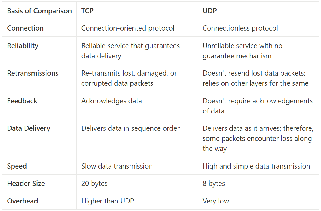
TCP vs UDP
Multiplexing and demultiplexing.
Multiplexing and demultiplexing involve transmission of data from unrelated applications and other sources over a network simultaneously. The transport layer offers dedicated control mechanisms required to send data segments from different apps simultaneously.
Multiplexing improves efficiency when it comes to data transmission. It allows data packets from the same destination (differentiated by their port numbers) to travel along the same network path.
On the other hand, demultiplexing service allows the receiver’s side to obtain data streams coming from different processes. It splits a network connection among several paths to enhance the throughput.
Port numbers play a crucial role in achieving both multiplexing and demultiplexing services at the transport layer. Port numbers help differentiate between different communication streams.
Flow control.
The transport layer controls the amount of data in transmission by imposing a range of flow control techniques between the adjacent layers of OSI model.
Sometimes a sending device may transmit data at an unacceptable rate. For example, it can send data at a faster rate, which is greater than the rate the receiving device can process. This then leaves the device overwhelmed with data.
Consider a computer connected to a server. Suppose a server can send data maximum at 80 Mbps while the receiver side processes data at 50 Mbps. With the help of the transport layer, the receiver can request a server to slow down data transmission rate up to 50 Mbps so that no data gets lost.
Similarly, if a server is sending data at 20 Mbps, the receiving device can request it to increase data transmission rate to 50 Mbps in order to maintain the system performance.
The well-known TCP protocol in the transport layer allows the acknowledgement of data as the receiver informs the sender of the size of data it can hold.
Flow control circumvents network congestion. Eventually, the data transmission process becomes efficient.
Window-Based Flow Control (Windowing).
Window-Based Flow Control is often colloquially referred to as “Windowing.” The term “windowing” is derived from the concept of a sliding window that is used in the flow control mechanism of protocols like TCP at Layer 4.
- Sliding Window: Description: TCP utilizes a sliding window mechanism where the window size begins with one segment. Acknowledgment: The window size doubles after a successful acknowledgment of the current segment. This acknowledgment is an indication from the receiver that it has received the data and is ready for the next segment.
- Exponential Increase: Description: The window size continues to exponentially increase upon successful receipt of each set of segments. This allows for more efficient data transfer.
- Limitations: Round-Trip Time (RTT): The window size may be adjusted based on the RTT, which is the time it takes for a packet to travel from the sender to the receiver and back. If the receiver does not acknowledge successful receipt within a certain time period (RTT), adjustments to the window size may occur. Maximum Window Size: The window size increase continues until a configured maximum window size is reached.
Segmentation.
Segmentation is an important part of the transport layer. Transport layer protocols break application messages into small data units, or segments, before passing them to the network layer.
Each segment has:
- A source port number
- A sequence number
A source port number helps direct each segment to the correct application. On the other hand, a sequence number helps reassemble data units in the right order to ensure correct messages at the receiver’s end.
Protocols split data into small chunks to avoid fragmentation. Note that TCP supports this while USP doesn’t.
Buffering.
Buffering is particularly relevant to Layer 4, where the management of data segments, flow control, and congestion control mechanisms are implemented.
With buffering, a device (for example, a router) allocates a chunk of memory (sometimes called a buffer or a queue ) to store segments if bandwidth is not currently available to transmit those segments. The buffer allows the device to store segments until they can be transmitted.
Buffers or queue has a finite capacity, meaning they can only store a certain number of segment. However, in the event of an overflow, segments may be dropped as the buffer becomes unable to accommodate all incoming data.
Buffering plays a crucial role in managing the flow of data and handling variations in data arrival rates between sender and receiver
In next articles we’ll continue navigating the next layers, till here, a brief of Layer 3 and 4.
LinkedIn: ![]()