5G/NR - QoS (Quality of Service)
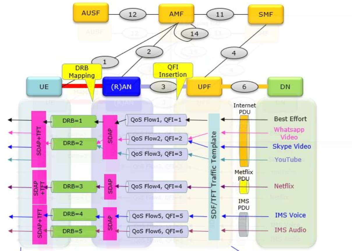
The QoS is determined / affected by almost every components involved in the communication between the parties of the commication, but major players determining QoS is those components on the bold lines in the UE + Network architecture shown below.
Those components are UE, AN (RAN, gNB), UPF (User Plane Function), DN (Data Network).
In this illustration, I illustrated a specific sample case of QoS flow so that you can make more tangible sense out of it.
As shown below, the user data would flow from a source (DN in this case) and final destination (UE in this case).
Each of the data packet goes though a specific PDU and Data Radio Bearer(DRB). Within these pipe line can be one or more imaginary flow with different level of priority, data rate, latency etc.
These imaginary flow is called a QoS Flow.
Each of those QoS flow would be eventually mapped to a specific items in 5QI table.
In order to meet the requirement in the selected 5QI, network need to configure all the elements from wireless physical resources through all the physical resources on core network interfaces.
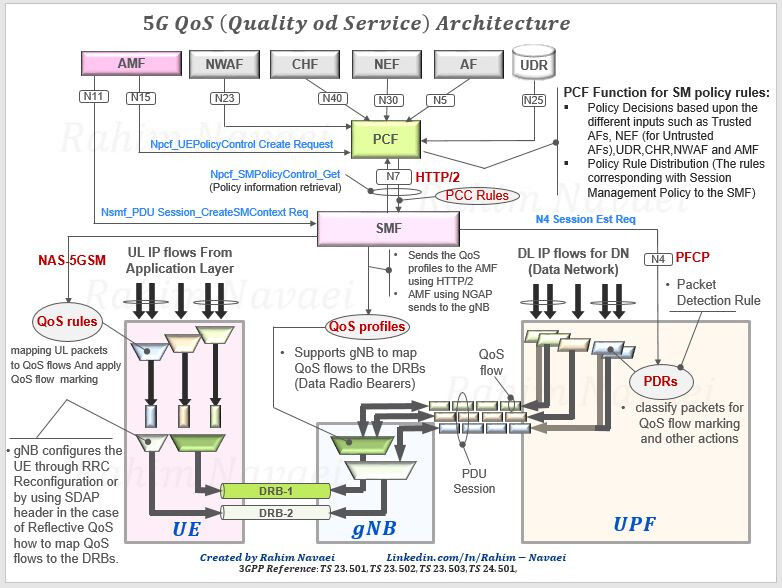
QoS Mapping in Signaling Message
The QoS flow is a logical pipeline defined for core network flow (more specifically for the data flow between AN(gNB) and UPF, in other words N3 interface).
For the wireless part, the data flow is managed in different flow called DRB(Data Radio Bearer).
To make a complete QoS pipe from the source of the data through the final destination, there should be some link (mapping) connecting the core network QoS pipe (i.e, QoS Flow) and AN pipe (i.e, DRB), and these mapping need to be informed to UE via signaling message.
The signaling message getting involved in the creation and mapping of QoS pipe is illustrated below.
The creation (definition) of QoS pipe on core network side is done by PDU Session Establishment Accept and the mapping between the core network QoS pipe and Wireless QoS Pipe(DRB) is done by SDAP configuration in a Rrc message (RrcSetup or RrcReconfiguration).
The Indicator (Identification) that connect the whole QoS pipe at every level is called QFI (QoS Flow Identifier).
- Mapping for Downlink Packet : The mapping between IP packet and QoS Pipe for downlink packet is done by UPF (i.e Core Network).
- Mapping for Uplink Packet : The mapping between IP packet and QoS Pipe for uplink packet is done by UE.
QoS Parameters
There are many different Parameters that are involved in NR QoS.
- 5QI
- ARP (Allocation and Retention Priority)
- RQA (Reflective QoS Attribute)
- Notification Control
- Flow Bit Rates
- Guaranteed Flow Bit Rate (GFBR)
- Maximum Flow Bit Rate (MFBR)
- Aggregate Bit Rates
- per Session Aggregate Maximum Bit Rate (Session-AMBR)
- per UE Aggregate Maximum Bit Rate (UE-AMBR)
- Maximum Packet Loss Rate
Many of those parameters are explicitly specified in signaling messages when a QoS pipe is created.
LinkedIn (Credits):