Hi Experts,
I am confused on frames structure of 5G.
Radio frames, SC, Slots, Symbols, Resource Elements, PRB, RB, REG, CRB, CP.
Anyone can explain it in a simple way?
Hi Experts,
I am confused on frames structure of 5G.
Radio frames, SC, Slots, Symbols, Resource Elements, PRB, RB, REG, CRB, CP.
Anyone can explain it in a simple way?
Thanks for sharing… I understand it…
Brother,
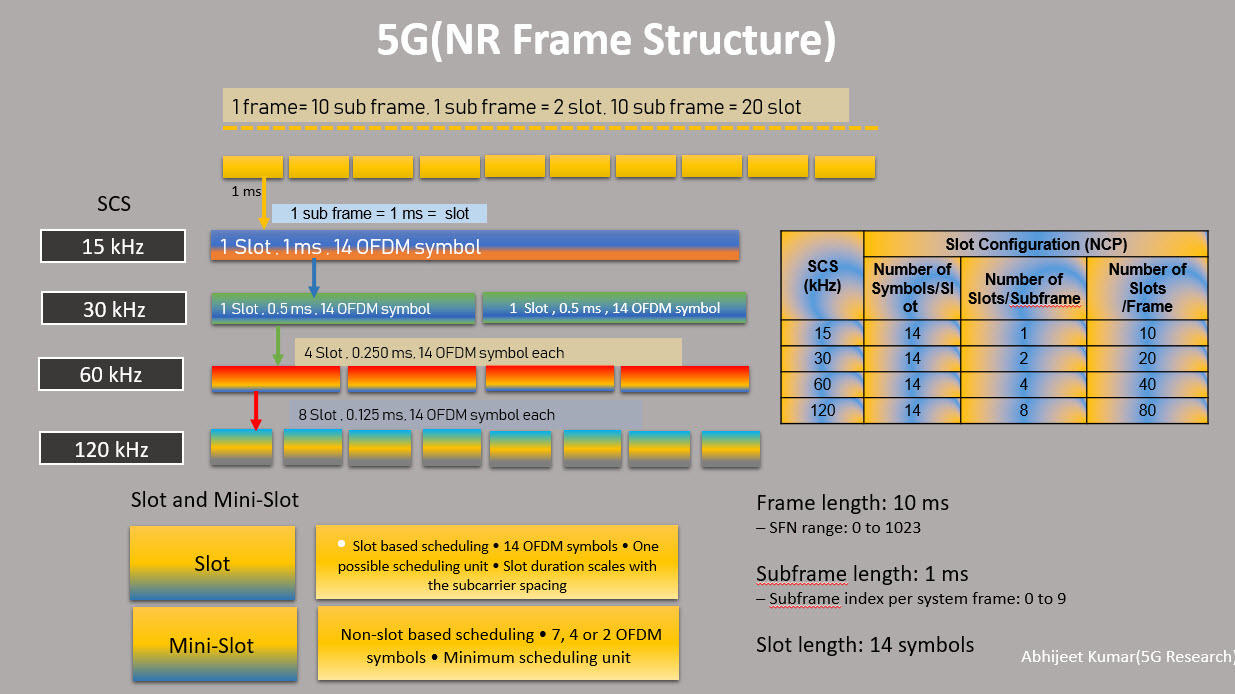
For Radio Frame.
Same thing like 4G. (1 Frame is of 10ms = 10 SubFrames( SFs ))
1 SF = 1ms (Differs as per the Numerology/SubcarrierSpacing (SCS)
Next change comes here where 1SF or slot (for scs 15Khz( 0 numerology )) = 14 symbols(Time Domain) and 12 Sub-Carries(Freq domain) Called as (ResourceBlock or Common Resource Blocks( CRB )
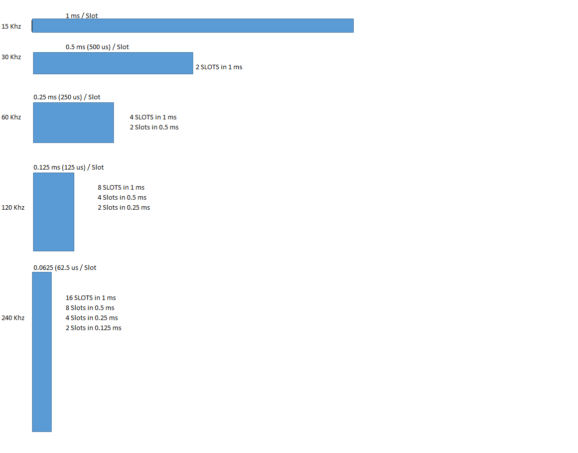
Based on the Numerology 0(15Khz),1(30Khz),2(60Khz),3(120Khz) or 4(240Khz) No of Slots changes per SubFrame(SF).
One thing to remember always is that Irrespective of Numerology, We have 14 symbols per Slot and only changes is TS duration and No of slots per SF according to numerology.
From the below snap, you might get clear with FS.
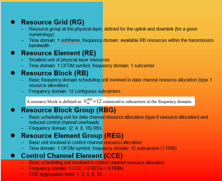
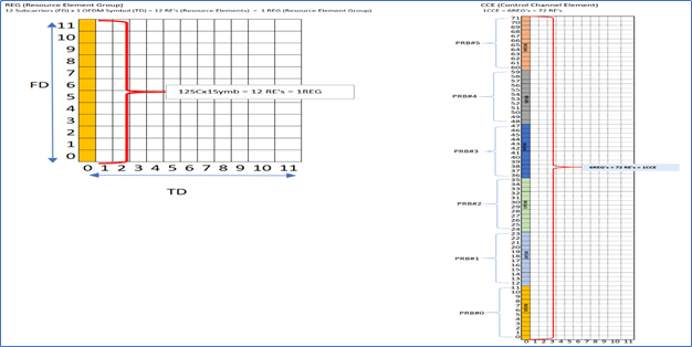
REG means Resource Element Group same as LTE which is used to defined control region only.
Major difference comes in REs and REGs.
In LTE, 1 CCE=9 REGs in which 1 REG = 4 REs, So total we had 36 REs in 1 CCE(9x4=36 REs) .
whereas in
5G, 1 CCE=6 REGs in which 1 REG= 12 REs in freq Domain(which is also called as RB, Little confusing right, Remember 12 SCs in freq and 1 symbol in Time domain we use to define CCE in 5G) So total we have 72 REs in 1 CCE(6x12=72 REs)
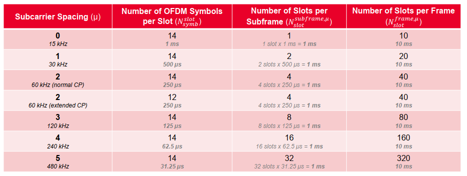
CP we have same for all Numerology. Only we use Extended CP for 2(60Khz) Numerology in which we have 12 symbols instead of 14. You can check above table for the same.
Below table is help you to quickly review and understand.
Thanks for sharing now I understanding well in 5G frames structure… I how CCE for aggregation level works in 5g…
Dear,
Below is the CCE detailed information.
PDCCH CCE Aggregation level:-
The number of Resource Elements (RE’s) of a CORESET that are required to carry a PDCCH DCI message is called “Aggregation level”, It is expressed in terms on CCE’s (control channel elements).
Number of REG’s/CCE’s that compose a PDCCH candidate is determined by the CCE Aggregation level, Aggregation level and number of CCE’s per aggregation are matched one to one.
Control Resource Set(CORESET) Resource Configuration:
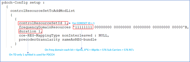
Based on the above configuration below is an example applying CCE Aggregation level for a DCI format.
1REG = 12SC’s X 1symbol = 12 RE’s
1CCE = 6 REG’s = 72 RE’s (54 REs are used for PDCCH, 18 RE’s are used for DMRS)
Total PRBs in the CORESET = 48
Total number of CORESET Resource elements = 576
Number of DMRS REs = 18 * 8 = 144
PDCCH RE’s = 576 - 144 = 432 (meaning In this case PDCCH candidate up to maximum Aggregation level 8 can be configured, Aggregation Level 16 is not possible in this case).
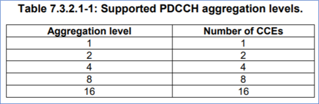
Following are 5 different PDCCH CCE aggregation levels supported in 5G NR, Aggregation Level 1, 2, 4 , 8 & 16 Each of these aggregation numbers specify the number of CCE’s (RE’s) that are required to carry a PDCCH DCI message(TS 38.213)
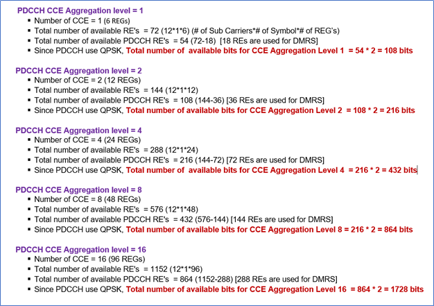
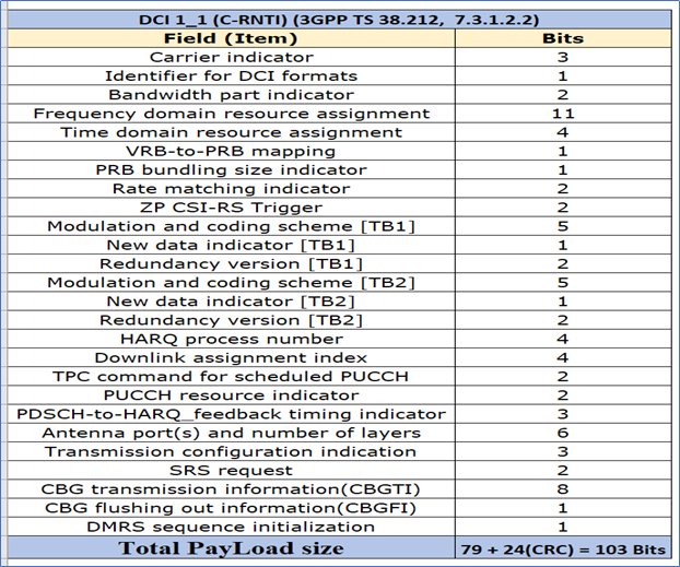
• Number of bits (Payload) of the DCI formats are less than the number of bits per each CCE aggregation level (as shown above).
• For example, Size of DCI format 1_1 scrambled with a C-RNTI for FR2 100Mhz (66RBs), the total number of bits after packing all the fields is 79 bits (referenced 38.212, 7.3.1.2.2) and after adding the 24 bit CRC, total payload size of the DCI 1_1 is 103 bits,
shown in below snap shot.
• In above example since DCI Format 1_1 is scrambled with a C-RNTI, assuming Aggregation level 2 is applied, meaning 103 bits payload of the DCI Format 1_1 is rate matched and bloated to 216 bits (applied aggregation level 2 = 2 CCE’s) giving a very good forward error correction protection for efficient decoding of PDCCH and derive the DCI message bits successfully.
• As per specification it mandates all DCI’s scrambled with a Common RNTI such as SI, RAR, Paging etc that have PDCCH candidates allocated in Common search space should always use highest Aggregation level 4 or 8.
• DCI’s scrambled with C-RNTI that have PDCCH candidates in UE Specific search space could use lower Aggregation level, This information is communicated to the UE via RRC Reconfigure message.
This is how “CCE” aggregation level works in 5G(NR). hope this will helpful you to understand this topic.
Checkout this video, it can answer some of your questions
@Ameen.
Hi, thanks for your informative data.
Can you introduce a reference that have stated the frame structure well.
Reasons for Multiple Numerology in 5G NR
NR operates from sub-1 GHz to 100 GHz using a wide range of deployment options (e.g., macro cells, micro cells, pico cells) and covers a very wide application range, including mobile broadband and several types of machine-type communications. A single OFDM numerology cannot fulfill the desired frequency range and all envisioned deployment options and applications without affecting system performance and efficiency
Cyclic-prefix overhead (delay spread) sets an upper limit for the subcarrier spacing; selecting larger subcarriers would result in an undesirable high CP overhead (degrading spectral efficiency).
Number of total subcarriers together with subcarrier spacing determines the channel bandwidth. So the subcarrier spacing is typically chosen as small as possible while still being robust against phase noise and Doppler effect and providing the desired channel bandwidth.
Smaller subcarrier spacings either results in a high error vector magnitude (EVM) due to phase noise or in undesirable
strict requirements on the local oscillator.
Too narrow subcarrier spacings lead to performance degradations in high Doppler effect scenarios
A mixed numerology concept implies the coexistence of multiple numerologies within one carrier in order to support numerous heterogeneous applications envisioned in 5G NR. The optimal choice of the numerology does not only depend on the service requirements (latency, reliability etc.) but also on the channel conditions imposed by the environment.
The unique choice of numerology cannot even be applied to a single use case family. For example, larger subcarrier spacings are required to achieve LL communications, since they provide shorter time slots. On the other hand, in a case when a channel delay spread is high, smaller subcarrier spacings
ensure a high reliability as another important service requirement within the uRLLC use case family.
The reason for this is that in such case the CP is longer, which prevents the system from ISI and reduces the probability of packet loss. The eMBB use case family seeks a high data rate, achievable at larger carrier frequencies, and exploiting larger subcarrier spacings. Large subcarrier spacings and
a small number of subcarriers are preferred for the MTC use case family since it requires a short-data
transmission and small packet sizes.
Nevertheless, a mixed numerology has a major defect, which is the Internumerology Interference (INI)
as a consequence of non-orthogonal subcarriers of different numerologies. In order to reduce this interference, an extra overhead in the sense of the Guard Band (GB) is employed.
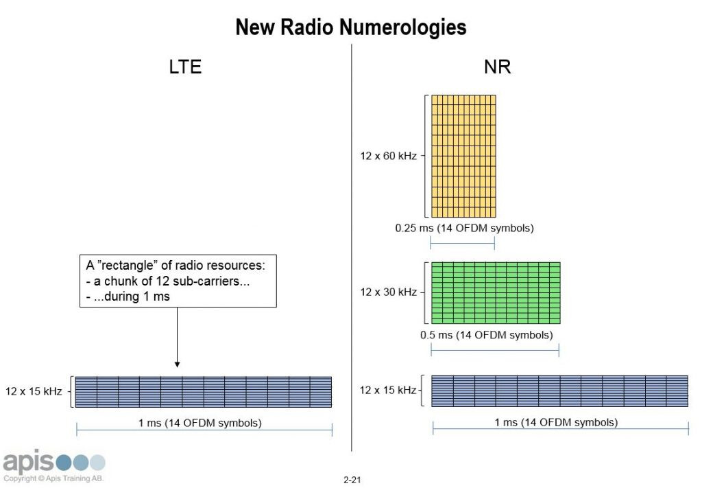
One of the new things in New Radio is better support for low-latency services. Not least the radio interface itself needs to be “faster”. But increasing the speed of the actual radio waves is – if not completely impossible – somewhat difficult.
So in order to decrease radio latency, some other tricks must be used. One of these is the concept of different NR Numerologies.
Reference and read More:
5G Flexible Numerology and application scenarios
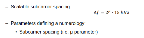
According to protocols, the subcarrier spacing supported by flexible numerology is 15 kHz, 30 kHz, 60 kHz, 120 kHz, and 240 kHz.
The 240 kHz subcarrier spacing is used only for sending downlink
synchronization signals.
The higher the frequency band is, the larger the subcarrier spacing is supported.
Flexible numerology applies to the following scenarios:
Delay: Different types of subcarrier spacing can be used for services with different delay requirements. A larger subcarrier spacing indicates a shorter slot, and the system delay can be shortened.
The uRLLC service can use smaller subcarrier spacing because of the lowlatency requirement.
Mobility: The Doppler shift varies with the moving speed. A higher moving speed indicates a higher Doppler shift. By increasing the subcarrier spacing, the system can improve the robustness of the frequency offset.
The high speed train can use a large subcarrier spacing because of the Doppler shift.
Coverage: A smaller subcarrier spacing indicates a larger CP length and a larger cell coverage radius.
Credits:![]()