Link Budget in 5G
Here we’ll see how is it calculated and why is it Iimportant & needed for Business prospective.
Read it for very crisp and clear information…
Based on current status it seems that most of the deployment of 5G network would be in very high frequency (millimeter wave) and this high frequency deployment would be one of the most important characteristics of 5G (NR). Looking at basic formula {Distance is inversely proportional to Freq. – Expecting more sites in 5G at very shorter distance based on these formula.}
One of the main use case of link budget is in pre-sale activity for 5g deployment proposal. Knowing (approx.) number of 5G sites will help the vendor and operator to estimate the cost and effort at time of deployment and making the network 5G ready.
The link budget is the calculation of total gain and loss in the system to conclude the received signal level (RxSL) at the receiver (i.e UE). The received signal level is then compared to the receiver sensitivity (RxS) to check if the channel status is pass or fail. Pass means that UE’s is received the Min. UL signal to communicate with the network.
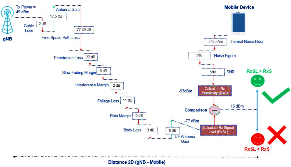
Received Signal Level at receiver (dBm) =
gNodeB transmit power (dBm) – 10log10 (subcarrier quantity) + gNodeB antenna gain (dBi) – gNodeB cable loss (dB) – Path loss (dB) – penetration loss (dB) – foliage loss (dB) – body block loss (dB) – interference margin (dB) – rain/ice margin (dB) – slow fading margin (dB) – body block loss (dB) + UE antenna gain (dB)– Thermal noise power (dBm) – UE noise figure (dB) – demodulation threshold SINR (dB)*
One of the Major difference between 4G/LTE and 5G link budget is Path Loss calculation.. To calculate the path loss , we use suitable propagation model for 5G (i.e we use 3D propagation models which gives us almost accurate path loss & real user received signal strength). Based on formula we can calculate the distance or say cell radius of gNB. These helps us to calculate the gNB footprint at time of site planning.
Path Loss (PL) =28.0+22 log10( d)+20 log10( fc)
Were, d = Distance & fc is center freq.
The reception sensitivity is mainly based on the capacity requirements (throughput) as SINR value is directly linked to how much throughput we want to achieve at the cell edge and to understand and get cell edge values identifying and calculating the cells radius is important.
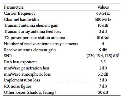
As per Japan - Docmo testing results they have classify below parameters values to calculate 5G Link budget, Major check points were they have done testing on 60 Ghz which is far far away spectrum and Ch-Bw was 500 Mhz.
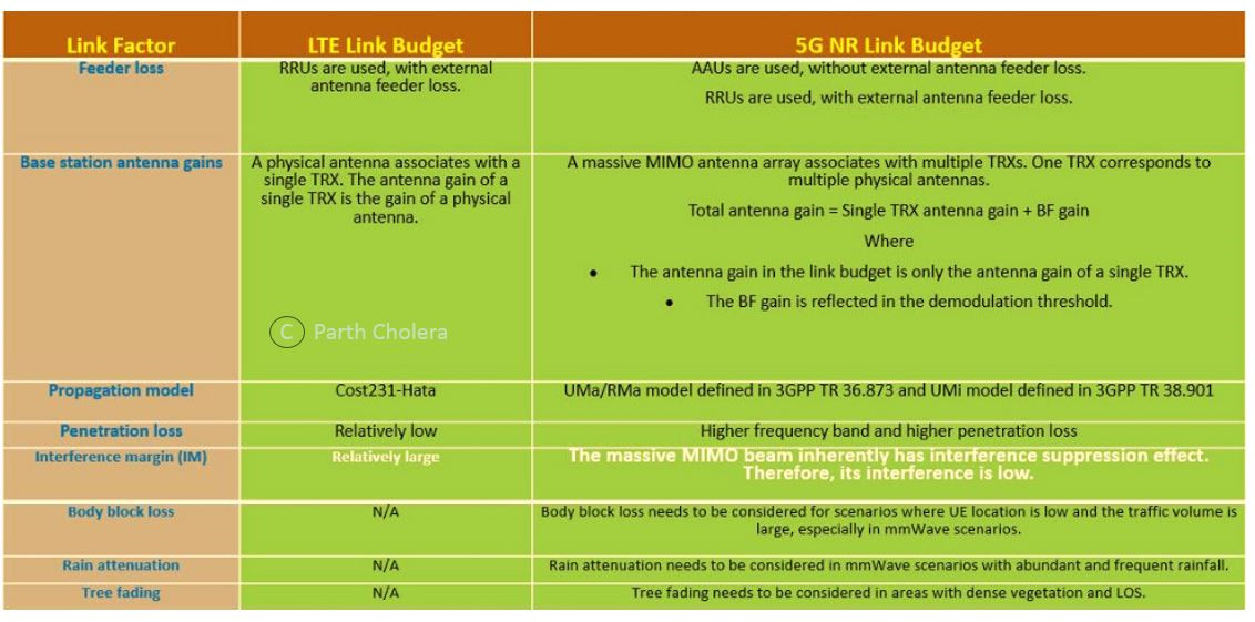
However One of the major difference between 5G and 4G is the Band which we are using [can’t be replaced or ignored] but they have no difference on the C-band. However, the body block loss, tree fading, rain attenuation, and snow/ice loss are introduced in 5G which was miss in 4G [Ref the Diagram below].
Link Budget 4G & 5G Comparison
Comparison of Link Budget between 4G & 5G with Major factors mentioned below::
5G Link Budget Example
Example to understand 5G Link Budget in better way…
Considering below assumption we have share the link budget result for different - different distance with Pass and Fail result. {Note some values can be higher for higher Freq. or clutter}.
- Type of coverage (Outdoor/indoor) ==> Outdoor
- 5G Propagation Model ==> Urban Macor with 3D model
- Direction of Link ==> UL (uplink)
- Centre frequency for Tx, MHz ==> 3410
- Number of PRB ==> 1
- Subcarrier Spacing (µ) cofiguration ==> 30 kHz
- Subcarrier Quantity (for TX power correction) = Number of used RB * Number of Subcarrier per RB ==> 12
- Noise figure (dB) ==> 4
- Target SINR ==> -2
- Cable Loss, dB ==> 2
- Antenna gain. dB ==> 17.5
- Antenna Height, m ==> 25
- Transmit power. dBm ==> 23
- Body loss, dB ==> 3
- Slow fading margin, dB ==> 7
- Foliage loss, dB ==> 8.5
- Rain/Ice margin, dB ==> 1
- Interference margin, dB ==> 2
Test Result [Considering above assumption]
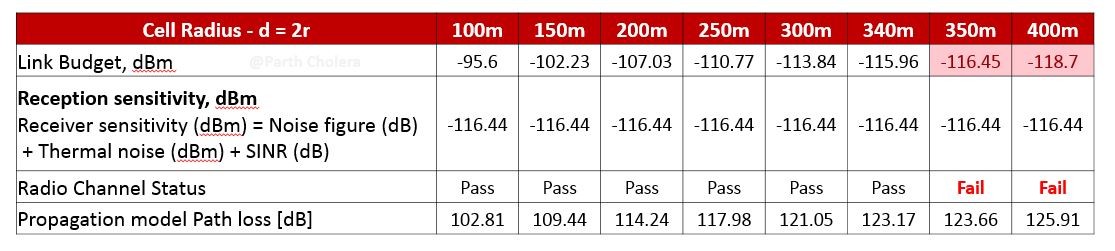
If we stretch that the link reach to 500 m, the path loss will increase to approximately 150 dB. This is doable, but it makes the radios on both uplink and downlink more complex, and the power consumption will increase dramatically. Highly not Recommended !!
Conclusion
Was the above information helpful?
Share with colleagues… Feel free to Add… Comment… Suggest…
You can also find me in Linkedin: https://www.linkedin.com/in/parthcholera/