2D, 2.5D, & 3D
![]()
![]()
![]()
In RF planning or radio network planning, we often hear this terminology, but it is quite difficult to differentiate what it is, in fact it is often mixed up between 2D, 2.5D, 3D map and propagation models.
Actually, 2D, 2.5D, 3D maps and 2D, 2.5D, 3D propagation models are different things but are related, especially if we use RF planning software such as Planet Mentum or Forsk Atoll.
Let’s extract each of them.
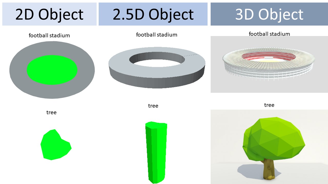
2D, 2.5D, 3D Maps ![]()
- 2D Maps are two-dimensional objects that are typically mapped onto the surface of geometric objects, or used as environmental maps to create a background for the scene.
- 2.5D Maps are two-dimensional objects projected with height to get 3D view (2D + Height).
- 3D Maps are profiling of objects in three dimensions to map the objects in the real world.
I hope image can explain more what the differences 2D, 2.5D, 3D object map.
RF planning software generally uses clutter maps (2D) as data in calculating wave propagation. By adding clutter map height data, the clutter map will become a 2.5D map.
As for using 3D maps, I don’t think there is any planning software that uses them.
However, if so, you can write software name & software version in the comments parts, please.
2D, 2.5D, 3D Propagation Models.
The radio propagation model describes the behavior of a signal when transmitted from a transmitter to a receiver. It provides a relationship between transmitter & receiver distance and path loss. From this relationship, we can get an idea of the allowable path loss and maximum cell range.
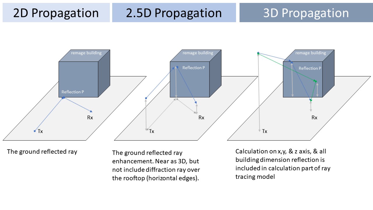
- 2D Propagation Model, a basic propagation model that uses 2D calculations (X & Y axes).
- 2.5D Development of a basic propagation model that takes into account transmitter antenna height, receiver antenna height and reflection point height.
- 3D Development of a propagation model that uses the X, Y, & Z axes, so that the direction of the wave emission, the angle of reflection and the direction of the wave reflection are all taken into account.
Example :
2D : Okumura, Hata, COST Hata, Standard Propagation Model.
2.5D: Quasi Ray Tracing Propagation Model, Pseudo Ray Tracing Propagation Model.
3D : Ray Tracing Propagation Model.
Maybe it will be seen more clearly through the following illustration:
Several RF planning software companies claim to use 3D propagation models such as Aster on the Atoll forsk, CrossWave developed by OrangeLab, Planet 3D Model (P2M), and etcetera. Whether they use 3D modeling or actually 2.5D, I don’t really understand.
However, there is scientific articles that I read that mentions CrossWave is categorized as 2.5D using the pseudo Tracing Propagation Model.
However, 3D propagation model calculations will definitely take a lot of time because of the many components that will be taken into account.
Maybe someone can explain in detail the real propagation calculations model that used by the planning software company, please comment below.
Hopefully it will enlighten those who read it.
Thank You. ![]()
![]()
![]()