CCE is PUCCH in Uplink.
And PDCCH in Downlink.
Without CCE no data.
Be it PUSCH or PDSCH.
If your UL CCE is 40 to 50 percent all the time it is issue.
No…for UL scheduling eNB uses DCI format 0.
PUCCH resource configuration is given in SIB2.
In 5G DCI, there is pucch resource field. But 4G DCI, I don’t see.
That is comnon pucch. All UE can use it. But when report CQI, UE should know which pucch resource is reserved for it.
In 5G also, similar concept.
PUCCH configuration is provided in SIB1 for SA.
For NSA, it is provided in RRC Reconfiguration during Sgnb addition.
For uplink grant. Remaining siso/mimo/csi/sr/harq ack nack cases are done by pucch which too consumes UL CCE.
PUCCH resources does not consume CCE.
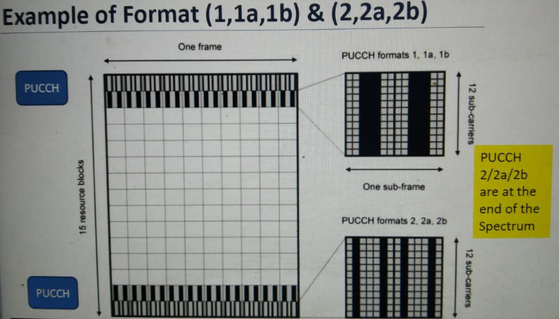
If you see PUCCH resources are always located at the end of the spectrum in 4G.
Correct. Also, PUCCH resources are only needed for DL.
If cause is CCE failure that means no more CCEs available.
That can impact DL and/or UL.
Format 1 has scheduling request too, in pucch format.
What’s this sr for?
That’s uplink grant assignment and this is uplink sr.
Sr always carry cce.
Uci is also for scheduling so you mean no cce there.
So why ul cce failure then?
Is a question.
And he has ul cce allocation failure that means cce are carried.
OK.
Then why ul cce failure happens.
Thats my question then.
You say no, I assume ok no cce in uplink.
Why ul cce failure seen?
Allocation.
It’s due to congestion.
Similar to DL CCE failure.
The UL grant always happens at n+4 in FDD.
If the UE receive DCI0 at sf n, it will send PUSCH at n+4.
So uplink congestion the KPI is ul cce allocation failure if no cce are there in uplink.
It should not reflect.
Ultimately eNB only allocated the CCE for UL transmission.
Yes obviously.
But this cqi parameters control is necessary if high cqi steps are there.
It will lead to this failures.
That’s why in TDD config 2, you will find high CCE utilisation in SF3 and sf7.
That’s the importance of reducing cce failure.
eNodeB gives cce, if ue send continous report througg pucch.
It’s consumption of cce in short.
That’s why continuous cqi accelaration degrades kpi.
So I suggested to make changes.
Cce is for dl, ultimalely ue reports through pucch.
Cqi periodicity is 40ms for example ur cce will be faster and if 80 ms cce will be low and more users can be granted but 40 ms gives good throughput and accuracy but high user case bad.
For scheduling.
And dci0 is only for aperiodic cqi case i feel.
https://www.sharetechnote.com/html/Handbook_LTE_CQI_PMI_RI_ReportingConfiguation.html
Sorry I went extreme for this, but it was a good discussion. ![]()
![]()
![]()
Correct, PDCCH and PUCCH resources are different.
Dear Hainm
Have you found the cause and solution ?
I have the same problem and need to know what to do
As you know, the main reason for CCE’s (UL & DL) failure is the lack of CCE’s resources.
Due to the difference in how resources are allocated in UL and DL, there is always a need to send more CCE for UL. (Of course, the activation of some features also aggravates this issue, like Prealocation scheduling)
Note : UL CCE and DL CCE Allocations (both of them) carried by PDCCH.
To increase PDCCH Capacity check following parameters and implement step by step
- PdcchPcSwitch:Off
- CfiAdjCceThld → INF
- PdcchPowerEnhancedSwitch : ON
PdcchPowerBoostUpperLimit : 6dBm - PhichResource : ONE_SIXTH
Other OPT action
PdcchInitialCceAdjustValue → 0
UlPdcchAllocImproveSwitch → 1
HLNetAccSigAggLvlSelEnhSw → ON
1 Like
what about increase PUCCH capacity?