If the LTE UE fails to combined attach and goes to UMTS network, how long until It attempts to attach again in LTE network?
UE needs to register with the network to receive services that require registration.
This registration is called Network Attachment.
The always on IP connectivity for UE is enabled by establishing a default EPS bearer during Network Attachment procedure.
Predefined PCC rules most common set in PGW will be applied for default bearer.
Attach procedure may trigger one or multiple Dedicated Bearer Establishment procedures to establish dedicated EPS bearer for that UE.
During the Initial Attach procedure the Mobile Equipment Identity is obtained from the UE.
The MME operator may check the Mobile Equipment Identity with EIR.
At least in roaming situations, the MME should pass the ME Identity to the HSS, and, if a PGW outside of the VPLMN (Visited PLMN), should pass the ME Identity to the PGW.
In you question, Attach Reject message will go in DL direct transfer message.
After receving Attach Reject UE will check the cause for the reject and it will re-try to attach based on the casue value given by MME.
Right…
But do you know the timers/parameters affecting it?
Here you can find a Initial UE Attach Process in LTE ( A concise description )
- The UE initiates attach process by transmission to eNodeB an attach request message in the form of id-initial UE message request together with RRC parameters indicating selected network and old GUMMEI. This message contains following parameters:
- IMSI or Old GUTI
- last visited TAI
- UE core network capability
- UE specific DRX,
- Attach type
- ESM Message container ( Request type, PDN Type, Protocol Configuration Options, Ciphered Option Transfer flag)
If the UE has valid security parameters, the Attach Request message shall be integrity protected by NAS MAC in order to allow validation of the UE by MME.
-
The eNodeB forwards attach request message to MME contained in S1-MME control message ( Initial UE message ) together with selected CSG network , CSG access mode, CSG Id and TAI+ECGI of the cell where it received the message to the new MME.
-
The MME selects Serving Gateway on serving gateway selection function and allocates an EPS Bearer Identity for Default Bearer associated with UE. Then it sends create session request message to the selected serving Gateway function. Create Session request message contains following parameters:
- IMSI
- MSISDN
- MME TEID for control plane
- PDN GW Address
- PDN Adrress
- APN RAT Type
- USER CSG Information
- Default EPS Bearer Qos etc…
- The serving gateway creates new entry in its EPS Bearer table and sends create session request to P-Gateway indicated by PDN Gateway address received in Previous message. Create session request message contains following parameters:
- IMSI
- MSISDN
- APN
- Serving Gateway address for the user plane
- Serving Gateway TEID of the user plane
- Serving Gateway TEID of the control plane
- RAT Type
- Default EPS Bearer Qos
- PDN Type
- PDN Address etc…
After this step serving gateway buffers any downlink packets it receives from PDN Gateway without sending downlink data notification to the MME until it receives modify bearer request message on later part. MSISDN is included if it is received from MME.
- The P-Gateway creates a new entry in its EPS Bearer context table and generates a charging ID. The new entry follows the P-GW to route user plane PDUs between S-GW and and Packet Data Network (PDN) and to start charging. The PDN Gateway returns create session response message to the Serving Gateway. This message has following parameters:
- PDN Gateway address for the user plane
- PDN TEID of the user plane
- PDN TEID of the control plane
- PDN Type
- PDN Address
- EPS Bearer Identity
- EPS Bearer Qos
- Protocol configuration Options
- Charging ID etc…
PDN Gateway takes into account received PDN type, the Dual Address Bearer Flag and the policies of operator when PDN Gateway selects PDN Gateway to be used.
-
The Serving Gateway return create session response to new MME. It contains PDN Type, PDN Address, SGW for User Plane, SGW TEID for user plane etc.
-
The new MME sends an Attach accept message having parameters like APN, GUTI, PDN Type, PDN Address, TAI List, EPS Bearer Identity, Session Management Request, Protocol configuration, NAS Sequence Number etc … to the eNodeB. GUTI is included if new MME allocates a new GUTI. This message is contained in S1_MME control message Initial Context setup request.
-
The eNodeB sends Radio Resource Control Connection Re-Configuration message including EPS Radio Bearer Identity to the UE and Attach accept message is sent along to the UE. The UE store the Qos negotiated, Radio Priority, Packet flow Id and TI which is received in Session Management Request for use when accessing GERAN or UTRAN. The APN is provided to the UE to notify it of the APN for which the
activated default bearer is associated. -
UE sends RRC configuration complete message to eNodeB.
-
eNodeB sends initial context setup response to MME. Initial Context Setup response message includes TEID ( Tunneling End ID ) of eNodeB and the address of the eNodeB used for downlink traffic on S1_U reference point/interface.
-
UE sends direct message to eNodeB which includes Attach complete message.
-
eNodeB forwards the Attach Complete message to the new MME. in uplink NAS Transport message.
After the Attach Accept message and once the UE has obtained a PDN address, UE can then sends uplink data towards the eNodeB which will be tunnelled to Serving Gateway and PDN Gateway.
- Upon reception of both Initial Context Setup response message and Attach Complete Message , MME sends Modify Bearer Request to SGW.
This Completes UE initial Attcach Procedure.
- The Serving GW acknowledges by sending Modify Bearer Response (EPS Bearer Identity) message to the new MME. The Serving GW can then send its buffered downlink packets.
Henceforth, the data that was getting buffered at S-GW is sent to UE.
Here you can find some reasons for the LTE_AttachReject, and how this will affect UE behavior.
http://www.sharetechnote.com/html/Handbook_LTE_AttachReject.html
As you can see, depending on Reject Message, UE will retry in different ways.
2 Likes
hi i am not expert but
as mentioned in (lte optimization engineering handbook)
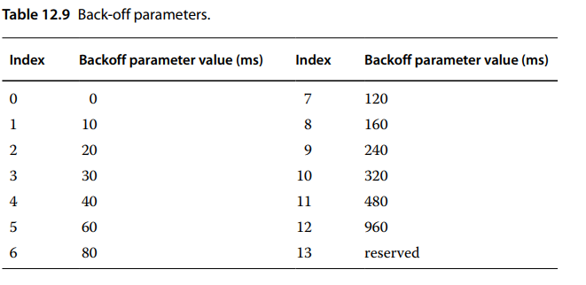
If the random access response or the contention resolution fails, in order to decrease
the collision rate, the UE backs off for a certain period of time selected randomly in the range
[0, rABackoff], then restarts the procedure to makes an immediate re‐attempt. The indication
of BackOff is in MAC control element. In a live network, it is better that BackOff can be automatic
adjustable, the more preamble transmissions, the bigger the value is. The Backoff parameters
are shown in Table 12.9
1 Like